6.3. Recording
6.3.1. Recording Interfaces
The Recording Interfaces Setup page is where you configure the loggers recording functionality. Because of the real-time nature of recording, and the large number of editable parameters (a recorder could have over 500 channels installed each with dozens of configurable parameters), special care has been taken to streamline the workflow of editing boards and channel configuration. Hence, this page does not follow the same convention that most of the other pages follow. The primary difference is that instead of editing settings and then having to click a ‘Save’ button to take effect, when you are on the main Recording Interfaces page changes take effect immediately. Trying to adjust gain one decibel at a time while viewing the results on a level meter, for example, would not be possible without a live environment as it would take countless tweak, submit, check cycles. Note that even if your Web browser does not support the dynamic nature of editing directly on the live page, you will still be able to edit channels using the ‘Edit Channel’ page for making changes.
A Board on a NexLog DX-Series™ recorder is another name for “Recording Interface”. The term comes because most Recording interfaces are exactly that, PCIe Boards installed in the recorder, but there are also Virtual Boards, such as VoIP Boards, which are not physical boards in the system. Each board has its own configuration settings, and one or more channels that exist on that board. For example, an Analog board with connections for 16 analog channels (2 wires per channel) would be considered a “16 Channel Analog Board”. Physical boards are constrained to a certain channel capacity via hardware. To change an 8 Channel Digital board to a 24 Channel Digital board requires physically removing the board and purchasing and installing a new one. Virtual Boards can often have their channel capacity expanded simply by purchasing a license and reconfiguring them, provided the recorder has enough capacity to handle the additional channel load.
There are two kinds of Recording Interfaces: Internal and External. Internal sources are the boards, physical or virtual, discussed in the paragraph above. External Interfaces are systems that are connecting via Centralized Archiving, such as a second Recorder or an Eventide Smart Gateway.
6.3.1.1. View Modes

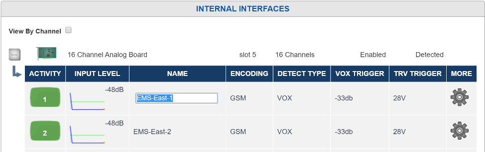
Fig. 6.18 Recording Interfaces
6.3.1.2. Navigation
With View By Channel disabled, the Recording Interfaces page will show one Installed Board Per row. The left most icon that looks like a Plus sign will expand the board so that all of its channels can be viewed below it and the plus sign will turn to a minus sign. Clicking that minus sign will “roll up” the channels into the board. Clicking on the Boards row will bring you to the Board Configuration “Edit Board” page where board settings can be modified. This page will be discussed in detail below. The next two columns display the board type (e.g., Analog, or Voice over IP), and the number of channels on the board. There will also be a column that tells if the board is enabled or disabled. Boards that are disabled are not currently recording. For physical boards there is an additional field that tells if a board is “Missing” or “Present”. A Missing board is one that was previously in the system, but has been removed. The board configuration and all configuration settings for it remain in the database. To remove the configuration settings and board entry for the missing board, you can delete the board from the ‘Edit Board’ page.
Expanding the board entry to display channels, or using the ‘View by Channel’ option will display one row for each channel. Each channel row shows seven configuration settings for the channel along with a “More” button for displaying all options for the selected channel on one page. To see and edit all settings in a non-live environment for a single channel, you can use the “more” button. It is often more convenient to modify channels settings directly on this page where they take effect immediately and you can see the values for multiple settings and channels at once. However, there is only space to display seven options on this page and there are many more than seven available options per channel. The seven fields default to the most commonly configured options, but you can click on the header above the table showing the channels to modify what field shows in that column to display a dropdown list of available column types to choose from.
6.3.1.3. Editing Values Inline
To edit a value, simply click the cell you want to edit, for example, Channel 12’s channel name. The cell will change to an edit control and when you click out of the cell or hit return, the value you changed will take effect immediately. Most options are either edit boxes where you can type your value, such as a Channel name, or a dropdown list where you select an available value from the list, for example Detect Type. A few options are represented as checkboxes or sliders where appropriate.
The down arrow key will submit the changes for the current cell being edited and select the cell below for edit.
The escape key will cancel an edit and set the cell back to the original value
If you want to change a channel value for all channels in a board at once, a shortcut is provided. Click on the header of the column you wish to change, and scroll up to and select ‘Set All’. The column header itself will change to an edit control and changes made there will take effect for all channels in the board, for example to change the VOX Threshold of all channels on an analog board to the same value at once. In addition, you can select “Insert Column” to insert an additional column into the table.
Doing a “set all” on certain fields trigger special actions other than setting all of the channels to the value specified.
Name: Appends the channel ID relative to the board to the end of the specified name
RTP IP: increments the last Octet of the address unless the value is “127.0.0.1 or “dynamic”
RTP PORT: increments the port number starting at the specified port. In addition, two ports can be specified to be mixed together delimited by a “,”.
In addition to all the editable parameters for channels, there are a few special “read only” informational fields that are available for display including the Channel’s ID, Board, and BoardID, as well as an activity indicator. The activity indicator is a real time indicator of the channels status. Grey means disabled, Green is idle, Red is recording, Yellow means user disabled.
The meaning of the editable fields will be discussed in the “Edit Channel” page discussion below as the parameters there are the same.
6.3.1.4. Detail Level Graph
Clicking on channels “Input Level” parameter will expose a panel called the “Detail Level Graph”. The Detail Level Graph will give a histogram of channel levels. Note that this is only useful on certain recording interfaces.

Fig. 6.19 Recording Interfaces Detail Level Graph
The Channel Level Details view provides a precise way to configure recording parameters. The yellow line indicates the current recording trigger point. The current channel being viewed can be seen in the channel status indicator. Note that changes to recording parameters take effect in real time, but do not effect historical information.
6.3.1.5. Edit Board
This Configuration Manager allows all of the settings and information about an individual board to be displayed and modified. To edit a board, click on the row describing the board from the main Recording Interfaces page.
No changes made to settings on the ‘Edit Board’ page will take effect until the ‘Save’ button is clicked.

Fig. 6.20 Edit Analog Board
The first tab, “Edit Board”, contains the options available to be configured for this kind of board.
The “Information” tab contains information and status about the board.
The Board Name: e.g. “16 Channel Analog Board”
Serial: The board’s serial number. For a physical board the serial number is actually burnt into the boards ROM. For a virtual board, this is a GUID (Unique ID) created when the board was added to the system
Channels: The number of channels the board contains
Position: Boards added to the system are numbered starting at zero. This is the number of the board. This is not the physical position of the board
Address: The physical location of the board. For a physical board it’s the PCI Bus and Slot number, for a Virtual board it’s the IP address of the board resource
Detected: For a Physical board, zero if the board is missing, 1 if it’s detected. Undefined for a virtual board
Code: This is a status code for the board. The normal state should be “RI-FAIL-NONE”.
The “Alias Banks” tab shows a list of any Alias Banks configured for the channels of this board. You can jump directly to any Alias Bank by clicking the name of the Bank in this list. See Alias Banks.

Fig. 6.21 Alias Banks tab of Board Edit
All boards also have an “Enable” checkbox to enable or disable a board. By default, when boards are added to the system they are enabled. Note that if you disable a board it will not record. It may be necessary to disable a board if you’re upgrading to a board with a higher channel capacity or if the board is malfunctioning and needs to be replaced. In some installations it’s a good idea to disable a board before making settings as to not make recordings before, for example, naming your channels.
The remainder of the informational and editable fields on the ‘Edit Boards” page are dependent on the board type:
6.3.1.6. Digital PBX Tapping Board
Synway PBX 8-channel, 16-channel, and 24 channel versions
Firmware Version: The version of the firmware loaded onto the PBX card, for diagnostic purposes only.
PBX Type: For a PBX Board to be able to record from a PBX, the PBX Type configured must be set to the model of the connected PBX. For PBX Model, version, and phone set compatibility, please contact Eventide.
Telco Encoding: This is the companding used on the digital voice sent between the PBX and the Phone. This is the format of the voice actually sent across the wire and is unrelated to any companding or compression codecs used to store the data on the recorder itself. If this is set incorrectly for your PBX, the recorded audio will sound scratchy and overdriven. MULAW is generally much more common than ALAW.
6.3.1.7. Analog Boards
8-channel, 16-channel, and 24 channel versions
Slot Type: This board is either PCI or PCIe
Notch Frequency: The Analog Board provides a Notch Filter to Notch out tones in the input signal. The frequency to notch must be configured on a board wide basis. In addition, the Notch Filter needs to be enabled for each channel on the board, so you configure the frequency here, and then which channels on the board it should be applied to.
Enable MDC1200: If enabled, this board will process MDC1200 Radio tones which provide RadioID information (who is talking) on some Analog Radio systems. In addition, an add-on license key must be installed to allow the feature to be utilized and a User Defined Field (Recording: User Fields) must be added to the database to hold the RadioID. The field should be called RADIO_ID
Enable Time to Answer: When enabled, this will provide time in milliseconds between first ring and when the reciever goes off-hook. This only works with channels set to HOOK Detect type.
Extended Beep: If enabled, the beep for this board will be 1400 Hz and 424 ms, which is within the 1400 Hz ± 1.5% and 400ms ± 75ms specification for Australian requirements for beep on line recordings. (Beep is only available on PCIe analog boards.kc)
Beep Gain: Allows you to adjust the volume of the beep from -21db to +18db, in 3db increments, relative to the default level.
6.3.1.8. T1/E1 Board Active and Passive Boards
These boards come in Single Port and Dual Port versions for recording one or two T1 or E1 Trunks. The Dual Port versions simply provide the same configuration options separately for each Port. For each port the options are as follows:
Port Type: Whether the Trunk is a T1 or E1 (must be the same on both ports on a dual port board)
Protocol: The Protocol used on the T1/E1. Options are None (Recording is VOX Only), ISDN, or CAS/RBS
Protocol Variants:
Line Coding: Whether the Line coding on the T1/E1 is AMI, B8Zs or HDB3
Framing Format: Whether the Framing format is SF, ESF, G704, or CRC4
Interface Side: TE or NT. For an active board, this needs to be set to the opposite of the setting on the equipment terminating the other end of the T1/E1. For passive boards this can normally be left at the default setting, which is TE.
Passive T1/E1 Boards are used for tapping between two T1/E1 endpoints, both of which terminate their end of the T1/E1 circuit, with the recorder passively listening in between by use of a ‘T-adaptor’ wiring tap. These are typically used for tapping and recording a T1/E1 circuit, for example, between a PBX and the telephone company, where the recorder is not involved in the communications and just listening in the middle.
With an active T1/E1 the board will terminate one end of the T1/E1 connection. If the board is configured for ISDN call control, the recorder will also answer calls placed over the T1/E1 link and record all the audio sent to it during the call. The recorder will never place a call to the remote end over the T1/E1.
6.3.1.9. Eventide RTP / VoIP Virtual Boards
See Recording VoIP or RoIP Calls.
6.3.1.10. Edit Channels
Clicking on the gear icon next to a channel allows you to set channel level parameters. Note that most of the common parameters for a channel can be configured in the main table channel table as well by clicking on a cell.
In addition to editing channel information inline you can also edit it by clicking the gear icon.
Note
Some options described below are only available on some kinds of boards and not on others.

Fig. 6.22 Edit Channel
Encoding: The field is editable and sets the encoding algorithm.
6.3.1.10.1. Choosing an Encoding Algorithm
The following encoding algorithms are available:
13 kbit/s GSM (factory default)
16 kbit/s G726
32 kbit/s G726
64 kbit/s MuLaw
The data rate indicates the amount of storage used per second of recording. The default will give you the most channel-hours. Encoding algorithms always represent a compromise between storage space and perceived quality. All the algorithms listed are general-purpose, and are not restricted to voice. You might want to select either the 32 or 64 kbps algorithm if your recordings are going to be used by other decoding equipment, such as with fax recording. Fax in particular is very sensitive to the compromises made in reduced-bit-rate encoding. The human ear is much less so.
You can experiment with these algorithms to get the best balance between sound quality and storage space.
Name: Editable with an external or on-screen keyboard.
The channel name can be up to 64 characters. It can identify the signal source for each input channel. Telephone number, radio station call letters, ATC frequency and function, or any other free-form data may be entered here. While up to 64 characters of data may be entered and saved, display constraints suggest that you choose the first few characters most carefully. There is no requirement to modify these identifiers. The factory default “Channel 01” … “Channel nn” may be serviceable.
Enable AGC: Activates or deactivates Automatic Gain Control for Analog channels. Automatic Gain Control assures that recordings take advantage of the full dynamic range of the recording process. If you record at too high a level, the signal will “clip” and sound very distorted. If you record at too low a level, the signal will sound very soft and have a poor signal-to-noise ratio. Enabling AGC gives extra margin when recording telephone calls where the local party may be much louder than the distant one-it will boost the gain by up to 24dB when the distant party is speaking. AGC should be enabled in most cases. It can be disabled in installations where audio levels are well-controlled (e.g., broadcast radio stations).
Enable Notch Filters: Enables the Notch filter for this channel. The frequency for the notch is set at the board level.
Enable Beep: Enables a “Beep tone” to signify to callers that the call is being recorded. Activating the beep places a short, distinctive tone on the respective channel of the input connector. This tone is approximately 65 milliseconds in duration at a frequency of 1455 Hz. It serves to indicate that the call is being recorded, and is required by some state laws. Of course, the beep will only be audible to the callers if the recorder is connected directly to the telephone line in question; if an amplifier or other device is interposed it will serve no purpose. Beep tones are only generated on Analog Input Boards, not on Digital PBX or T1/E1 interface boards.
If extended beep is enabled (at the Board Edit page), the beep will be 1403.508772 Hz and 387.5 ms, which is within the 1400 Hz ± 1.5% and 400ms ± 75ms specification for Australian requirements for beep on line recordings.
DETECT: This parameter determines when an input channel is active and should be recorded. It establishes the primary recording control for the channel.
Analog Boards: Always, Disable, GPIO, Scheduled, Tip/Ring Voltage, Vox.
Digital Boards: Script, Always, Disable, Vox. (Display-Only: Off Hook, Data Channel.)
Local VoIP: Varies by RTP/VoIP template configured.
Screen: Always, Script, Disable, Scheduled, User Activity.
The following are valid values for this parameter:
VOX: (default) Starts recording if the voice (vox) or audio input signal is above the configured Vox threshold setting, and stops recording if the signal drops below that setting for the configured hold time.
TRUEVOX: [RTP only.] In regular VOX mode for RTP channels, the presence of data on the line will trigger recording, but some environments will transmit large durations of data that is actually silence, so this mode will analyze the contents of the packets and evaluate recording based on the volume of the contained audio.
TRV: Starts recording if the DC input voltage is lower than the configured TRV (Tip-Ring Voltage) threshold, indicating an off-hook condition, and stops if the voltage rises above the configured setting for a period equal to or greater than the configured TRV Hold time. Note that TRV detect is only available for Analog boards and is only useful for audio sources that provide this DC voltage in addition to the analog signal (such as standard analog phone lines)
On: Records the channel continuously. For voice, audio, or call recording, it records regardless of input signal or voltage conditions. (This is useful if there are periods of silence that need to be recorded, such as dead air on a broadcast station or long periods of dead silence in a courtroom.) For screen recordings, the recording includes when the screen saver is on. This setting is not affected by the Activity Timeout or Inactivity Timeout parameters.
Note
If recording in On mode, it can be helpful to break the recording into smaller segments (such as 1-hour segments).
On Voxbreak: This is a detect type that is available specifically for Analog boards. It is a combination of On and Vox modes. Like ‘On’ mode above, it provides continuous channel recording, and like Vox mode it breaks calls into segments based on the VOX threshold. When the level of the audio input being provided is above the channel’s configured VOX threshold, the recordings will be tagged with calltype Audio. Once the VOX Hold Time setting on the channel has elapsed, the channel will break the call and continue to record, tagging this new recording with calltype Inactivity until the VOX threshold is met again. This detect type is useful for sites that want to have 24/7 coverage while still being able to quickly find periods of activity or inactivity on the channel in MediaWorks DX™.
GPIO: Uses an input signal from an optional General Purpose Input/Output (GPIO) board to trigger recording start and stop. The pin pair that carries the input signal is specified in GPIO Pin column. Recording starts on a high signal and stops on a low signal. This allows a variety of external devices to trigger recording.
Scheduled: Uses Scheduled Recording to start and stop recording.
Script: Records based on start/stop requests from the NexLog DX-Series™ Recorder itself. This is used in conjunction with custom scripts or other specialized programming created by Eventide Customer Engineering as a contracted professional service. This setting is not affected by the Activity Timeout or Inactivity Timeout parameters.
Disable: Disables recording for the channel.
Hook / Audio: These options are used for VoIP and Digital lines. They make start / stop decisions based on the available signaling from the data source connected to the channel. The exact behavior is dependent on the source. For example on an ISDN PRI Channel, this causes the recorder to take cue based on the ISDN Call Connection messages on the line. On Some PBXs this will use the actual hook state of the phone, while others (which do not provide accurate hook state), the recorder will use combinations of lights, button presses, etc.
Note
Channels on T1/E1 boards may display a non-modifiable DETECT value of Data Channel. When using ISDN Protocol over T1 or E1, one of the channels on the trunk is reserved as a data channel and does not contain any voice data. The recorder will automatically set that channel’s detect value to Data Channel and grey out that channel on the front panel.
VOX Threshold: This sets the trigger level for recording when Record Enable Mode is VOX. A value between -48dB and 0dB is typical. The factory default is -32dB. This setting is only used for Digital PBX, T1/E1, and Analog boards. For VoIP, VOX detect mode triggers off the presence or absence of RTP traffic, not the actual levels.
VOX Hold: If Detect is set to VOX, this sets the number of seconds the channel will continue recording after the signal drops and remains below the threshold. The factory default is 8 seconds.
Setting this for too long a value will record long periods of silence at the end of transmissions or join two calls together; too short a value may break a single call into apparent multiple call records at pauses in the conversation.
TRV Threshold: This sets the DC voltage at which a phone line is assumed to be in the off-hook state and eligible for recording. On a normal, clean telephone line, this does not have to be set too finely. On-hook voltages are typically 40-55 volts, off-hook under 10 volts. The factory default of 28 volts will probably be suitable. Noisy telephone lines, lines at a great distance from the central office, and lines that are recorded at one location but answered at another can have unusual voltage profiles and may require adjustment. This setting is only available on Analog boards.
TRV Hold: If Detect is set to TRV, this sets the number of seconds the call will continue to be recorded after the telephone goes on-hook. The factory default is 5 seconds. The on-hook state is then considered to define the end of the conversation.
With a line that has normal ringing voltage on it (+/-105V at 20-30 Hz), TRV will also respond to the ringing voltage. This means that, with a default of less than four seconds, each ring will appear to be a separate call. By setting TRV hold to five seconds or more, with a normal ringing cadence only one call will be logged from the beginning of the ring to completion of the conversation.
If you have set a channel to TRV, a special (non-programmable) feature will detect and flag a disconnected line if the tip/ring voltage stays below 3 volts for 1 minute. If this happens, it generates a severity 2 (warning) alert indicating signal loss (Alert #9016). When the voltage equals or exceeds 3 volts, it generates the corresponding “Resolved” alert for Alert #9016 to indicate the signal is restored. TRV Hold setting is only available on Analog boards.
Input Gain: Gain (or attenuation) in dB of the input channel - used to set recording level on analog boards. Valid settings are -18db, -12db, -9db, -6db, -4db, -2db, 0db, +3db, +6db, +9db, +12db, +15db, +18db.
Input Level: Real-time display of signal input level - useful for setting channel gain. This is not an editable item. This information is very useful for diagnosing recording problems, such as one call being broken up into multiple calls. Note that depending on the detect type this can either be TRVolt readings or VOX readings. Input level is available for Analog boards.
TRV Level: This non-editable item shows you the real-time minimum, maximum, and current value of the DC voltage at the channel input. The current value will indicate if the phone is on- or off-hook; the Min and Max will show the highest (on-hook) and lowest (off-hook) voltages seen by the channel input. If the current value fluctuates over a wide range when you are not using the telephone, it probably means that the line is very noisy. This information can help you set the TRV Thrsh value or diagnose problems such as spurious calls. This setting is only available for analog channels.
Default Call Type: This is the value that will be entered into the Calltype field of all calls that come in on this channel, unless altered by a custom integration. See the discussion of Calltype in the section on Custom Fields below.
Enable 4Wire Mode: Pairs this channel with one adjacent such that the audio received on this channel and its pair are mixed into a single call record. If enabled on an odd channel, it will pair with the next channel: Channel 1 will pair with Channel 2. If enabled on an even channel, it will pair with the previous channel: Channel 6 will pair with Channel 5.
The settings for each channel are independent so that you can configure them as needed, but you can live monitor and playback calls as one channel. Audio and metadata from both channels are recorded if the conditions to record are met on either channel.
Enable TDD: Calls coming in on this channel with TDD (Telecommunications Device for the Deaf) text data will be decoded and the TDD text stored in the RTTsummary custom field. The text feed can then be viewed in MediaWorks DX™ when playing back the call. NexLog DX-Series™ supports decoding of TDD data encoded using Baudot codes at 45.5 baud utilizing 1 start bit, 5 data bits, and 1.5 stop bits. This feature requires the TDD Add-on License and an RTTsummary custom field. Without this feature enabled and licensed, the audio feed of the TDD will be recorded, but the recorder will not decode the text for display and search purposes.
Activity Timeout: Timeout value in seconds. When set, alert #3001 (“Channel was active for more than X seconds”) is issued if a channel is continuously active for longer than the timeout value. The factory default is to disable this function. This setting does not affect the actual recording of the call. It simply issues an alert.
Activity Timeout is useful for calling attention to open or defective telephone circuits. When a channel is set for TRV detection, a LOW voltage activates it. If the circuit is open due to a broken wire, the voltage will always be LOW, and the recorder will issue an alert if this condition persists. If you are going to use this feature, then you should set this value to one that is longer than any reasonably expected call or message to avoid nuisance alerts.
Inactivity Timeout: Timeout value in seconds. When set, alert #3002 (“Channel was inactive for more than X seconds”) is issued if there is no activity on the channel for longer than the timeout value. The factory default is to disable this function.
This setting does not affect the actual recording of the call. It simply issues an alert.
Inactivity Timeout is useful for alerting you to circuits that should have signals but do not. If you are monitoring a radio channel and the radio is turned off, the inactivity timeout will eventually call this to your attention. Likewise, an unused (but active and paid-for) telephone line can be identified with this feature. Of course, legitimate inactivity can span weekends and holiday periods. Setting periods too short can result in nuisance alerts.
GPIO Pin: Specifies a value indicating the input pin on the GPIO board that is used for triggering recording to start or stop. The channel will record with the input pin is pulled high by connected to pin 49 and will stop recording with the pin is pulled low by connecting to ground with any even numbered pin. (This field is used with the detect GPIO setting.)
For the 24-channel GPIO board, values are as follows:
0: specifies pin 47 (PA0) | 6: specifies pin 35 (PA6) |
|---|---|
1: specifies pin 45 (PA1) | 7: specifies pin 33 (PA7) |
2: specifies pin 43 (PA2) | 8: specifies pin 7 (PC4) |
3: specifies pin 41 (PA3) | 9: specifies pin 5 (PC5) |
4: specifies pin 39 (PA4) | 10: specifies pin 3 (PC6) |
5: specifies pin 37 (PA5) | 11: specifies pin 1 (PC7) |
PBX Digital Sync Errors: This column is only important for Digital PBX tapping boards; it is used for installation and troubleshooting. The data will look like this: 1.1 / 0.66 [2,1,0]. The first two numbers are signal levels in volts. The first of the pair is the level of the signal coming from the PBX, and the second is the signal level coming from the phone set.
The three numbers inside the brackets are the total error counts for the channel since the last reconfiguration or restart:
Sync errors are more general errors on the channel as a whole.
PBX errors are errors in the signal from the PBX.
Phone errors are in the signal from the phone.
These errors can signify problems and can affect recording: if the errors are increasing at a steady rate, it indicates that there is a problem with the telephone line connected to the recorder. However, if the error counts aren’t all zero but do not increase, it might not be an indication of a serious issue: for example, someone may have unplugged and then plugged back in a phone.
Problems can be caused by:
Line issues (bad taps, multiple taps, line lengths, tap lengths, marginal wiring between the phone and PBX).
Unsupported phone set or line card.
The wrong PBX is set in the board configuration.
6.3.1.11. Steps for Setting Levels, Thresholds, and Hold Times
It is undesirable for single conversations to be broken up into multiple calls. There is a slight lag between each stop and start, so some of the conversation will be lost. Setting levels and thresholds properly will help you avoid this condition. This applies to channels set for VOX detect.
If you are seeing this condition, or if you simply want to check how well the default parameters match your facility, try this procedure:
Disable AGC
Set the Input Gain. It should be set with signals that best match what will be seen during normal operation. Watch the values and adjust the gain so that the current value ranges between -6dB and -1dB while a signal is present.
Enable AGC (if desired). Not recommended for broadcast recording, recommended for communications or telephone channels.
Using the Input level or the detail levels graph note the VOX Cur value with no signal present, but with the cabling still connected to account for line noise. Then note the VOX Cur value with the lowest-level input signal that you are likely to see during use.
Set the VOX Threshold using the values from the previous step. The threshold should be higher than noise but lower than your lowest signal.
Another possible cause for conversations recorded on multiple separate calls is Hold time. This would apply to both VOX Detect and TRV Detect. Conversations with pauses longer than the Hold setting will generate a stop-recording signal. When the conversation resumes, a start-recording signal will create a second call. To determine if this is happening, listen to the last several seconds of a call. If you hear a pause in the conversation longer than the Hold time, followed by a second separate call of the same conversation, then the length of the pause caused the stop-recording signal. If you wish, you can increase the Hold time. The downside is that longer periods of silence will be recorded at the end of EVERY call on that particular channel. For example, a 15-second Hold time on Channel 3 will cause a 15-second period of silence to be recorded on every call on Channel 3.
6.3.2. Replace Board
This section allows you to swap boards in your system for similar boards. This is necessary in the unlikely event of hardware failure (due to a power surge) or to expand channel count by replacing an 8 channel analog board with a 24 channel board, for example. When selecting the board to be replace it must be removed from the system. The board that you are going to replace it with must be physically in the system and disabled. Disable the board by going to the ‘Boards’ setup page and selecting the replacement boards configuration. When you have a possible replacement candidate the Replace Board setup page will show a submit button. If you do not a valid replacement configuration the button will not be present and the text at the top of the page will explain why you cannot do a replacement.
The act of replacing a board transfers all settings to the new board. This includes channel ordering, channel names, and parameters specific to the board type.
6.3.3. Retention Settings
Eventide NexLog DX-Series™ Recorders store call data on their storage devices and provide a built in database for immediate retrieval and playback of recorded audio. Once the hard drives fill up with data, the oldest data will begin to be deleted from the system to make room for new data as new recordings are made. The Retention settings allow you to customize when this data is deleted.
Note: any Call Record which has been marked as “Protected” in the Front Panel or MediaWorks DX™ will not be deleted to make room for new recordings regardless of retention settings. If both Limit retention time and Limit recording count fields are disabled, then call records will only be deleted if the hard drives are too full to store new recordings. Enabling and setting “Limit retention time (days)” will cause all call records older than the configured number of days to be deleted. For example, if set to 60 days, the recorder hard drives will contain a rolling history of the past 60 days of recordings, assuming adequate disk space to contain 60 days’ worth of calls.
In addition, Limit Recording Count allows a maximum number of Recordings to be specified. If this number is surpassed, the oldest recordings on the disk will be deleted to restore this constraint.
The Limit retention warning time (hours) setting will trigger an active alarm if the archive pointer for any archive drive is fewer than X hours ahead of the retention setting. For example:
On a system with 60 days of recordings, with the Warning Time set to 48 hours, and only uses a NAS to archive, and that archive is usually up-to-date, if someone stops the archive to browse and then forgets to start archiving again later, an alert will trigger in 58 days warning that the recordings are in danger of being deleted before they are archived. If someone starts the archive again at this point, the alarm will resolve after the archive pointer gets ahead of that 2 day window. If instead, no one reacts, recordings will start to be deleted before they have been archived and a second alarm will happen saying that the archive pointer is now behind the retention time.
We recommend setting the Warning Time to something high enough that your organization can respond to an issue that has arisen, such as 168 hours, which is one week.
Note that these settings have no effect on Archives. Eventide recommends Archive settings be properly configured and archive media to be properly maintained to put in effect a policy of making sure all recordings are archived to one or more archive media before being deleted due to retention policy.
By default, the option Delete record history with media is enabled. This option deletes the call record and associated metadata from the recorder database when deleting the record media (audio or screen.) For most users, this is the correct choice, but if you want to retain all information about call records that have come into your recorder even if they can no longer be played or exported, disable this option.
6.3.3.1. Reserves
Changed in version 2021.1: Reserve for attachments now includes User Content Uploads
There are three more fields to configure: Reserve for Attachments, Reserve for Reports, and Reserve for Cache, all in megabytes. These fields allow you to set a limit on disk space consumed by attachments (including User Content Uploads), reports and cache. The defaults are fine for most users. Unlike the limit fields, these fields do not cause deletion when exceeded; instead, no more attachments can be added to incidents, nor can more reports be generated. The recorder will have an active alarm if the reserve limit is met, allowing the system administrator to either increase the space available or contact users to have them delete unnecessary reports or attachments.
6.3.3.2. Retention Filters
The Retention Filters tab lists all Resource Groups with Retention Rules enabled. These groups are configured at the Resource Groups page, and the edit Retention Groups button will take you to the Resource Groups page, with the group filter set to show just Retention Groups.
6.3.3.3. Advanced Retention Settings
Clicking the Advanced tab will expose some advanced configuration settings. You generally would not need to change any of these settings unless recommended by Eventide or your Eventide Dealer.
Delete Parent Media Record: Certain Custom Integrations purchased from Eventide are designed to break existing media records into multiple records. When this is done, this setting determines whether the original media record is also retained or deleted
Use Prefix on Ignore: Used with Some Custom Integrations for Motorola SmartZone recordings where the same recording will be recorded from two different towers. This setting will cause the secondary ‘backup’ recording to have its channel name prefixed with DUP_ for ‘Duplicate’
User Unknown as Channel name: Normally the channel name of a call will be assigned with the configured name of the channel it is recorded on. This value can then be overridden by a Metadata Feed or Custom Integration. If no value comes in from these secondary sources, the name remains the name of the channel. If this option is checked, and no value comes in via a Metadata feed or custom integration, then the channel name for the recording will be set to ‘Unknown’ instead of the name of the channel it was recorded on.
6.3.4. Resource Groups
This page allows you to view and manage Resource Groups. A Resource Group is a configured set of one or more resources available on the recorder, and the rules that apply to those resources. Resources are the call sources on a recorder, and they are identified by channel name, physical channel id, and talk groups. Leveraging these rules and groups allows you to gracefully administer your NexLog DX-Series™ recorders in a powerful and flexible way.
Resource Groups allows you to manage all policy for a set of resources, instead of having a separate channel group for each rule. For example, if you have a group of channels recording Fire Department calls and another set for Police, you can now have a Resource Group named Fire that contains all channels with names that start with Fire, that grants permission to the correct users and follows the legal requirements for keeping Fire recordings, all in one place.
6.3.4.1. Resource Group Rules
The rules available are:
Permission: Grant access to these resources to a list of users. The users can then use these resources when browsing, exporting, searching, live monitoring, etc., based on the other permissions they are assigned on the User: Permissions page or are currently granted by being a member of a User Group.
Archive: By default, an archive drive archives calls from all resources, but when included in an archive rule, only calls from the group’s resources will be archived on the drives configured. This way a recorder that is split between Fire and Police duties can archive its Fire calls to one drive and its Police calls to the other. Note that only one archive group can control a specific archive drive at a time; when a new rule is configured using a drive in use by another rule, it supersedes the previous rule. If you are unsure of which rule is in effect, check the Archive Configuration Edit page for an archive to see which is assigned.
Playback: Groups calls at record time such that they get played back simultaneously in ‘playback group mode’. If a resource in this group type is selected for Evaluation, the other resources will automatically be included in the evaluation form. This is useful for pairing or syncing an audio and screen channel together.
Record: Recording on all resources in the group will start if the configured “Master Channel” starts recording. The Master Channel must be specified by Resource Name.
Retention: Specify duration that the calls from the resources in this group will be retained before deletion. This number must be smaller than the global retention setting for it to take effect.

Fig. 6.23 Resource Groups
The main page is divided into two columns: the left displays all the configured groups, and the right shows all available resources, grouped in a tree by Named Resources, Physical Channels and Talk Groups. The groups can be individually filtered at the top, so that you can look only at groups that have Permission rules or Retention rules. The full list of filters is shown below.

Fig. 6.24 Resource Group Rules Menu
At the bottom of the left column there is a summary of the currently selected group, showing which rules are currently configured and active for that group:

Fig. 6.25 Resource Group Rules Status
6.3.4.2. Creating Resource Groups
There are three ways to create a new Resource Group. The easiest way is to use the New Group button at the top of the left column on the Resource Groups page found in the Configuration Manager under Recording. There also two ways to create new groups in right-click menus that are detailed as we encounter them in the discussion below. The New Group button will create a new group and bring up the Group Edit window for that new group. Here you can name the group, select which rules apply, and configure each of those rules.

Fig. 6.26 Resource Group Edit: Permission Group View
Here we have a Resource Group named Front Hall, which has an active Permission Rule, granting users DJones, KPark, NLanders and WKing access to the channels in this group. A new group created with the New Group button will have no resources, which can be added in the two column view. Rules can be disabled by unchecking the checkbox; the rule’s configuration will remain saved but not take effect while the checkbox is unchecked.

Fig. 6.27 Resource Group: Empty Group
6.3.4.3. Adding Resources to a Group
You can add resources to a group in a number of ways:
The named resources and physical channel numbers in the right column can be clicked on to select them. Use Ctrl+Click or Shift+Click to select more than one at a time. Highlight a group in the right column by clicking on it. Then add the selected resources by clicking the leftward facing arrows between the columns.
Select resources and a group in the right column as above, and then Right-Click them to reveal a pop up menu that allows you to Add to Selected Group.
That pop-up menu also allows you to create a new group with these resources; it will open the group rules editor so that you can name and configure this new group.
You can also select resources and click+drag them from the right column into the group you want them to be added to.
You can right-click the name of the group and select from a menu, as seen in the figure below. From this menu, you can add a Name Filter, using * as a wild card to match multiple resources by name.
This menu also allows you to add a Channel Filter, with which you can specify a range of resources by physical channel ID and their source, which defaults to Local. The source field is only relevant to configurations involving resources on the recorder originating from Centralized Archive sources; if you want to group these, enter the serial number of the Centralized Archiving source into this field. Click the X to cancel and the Checkmark to save.

Fig. 6.28 Resource Groups: Right Mouse Button Menu
6.3.4.4. Deleting a Resource Group
You can delete a resource group in two ways:
Select the Group in the left column, and click the X button between the columns.
Right-Click on the group and select Delete Group from the pop up menu.
In both cases, you will be prompted to be sure that you really want to delete the group.
6.3.4.5. User Groups and Default Resource Groups
Resource Groups integrates with User Groups, in that a User Group can be configured to have User Permission Defaults. These defaults are a template rather than an active rule set. Defaults are granted to users when they are added to the group, but if the group’s defaults are updated, the changes are not applied to the current members of the group.

Fig. 6.29 User Group Edit
Following the behavior of previous NexLog DX-Series™ versions the Browse, Exporter, Researcher and Monitor groups by default have All Resources as a Default Permission. Unless configured otherwise, all users in those groups will have access to all local resources on the recorder.
If there are configured Search Groups on the recorder, you can also assign a selection of these as defaults for the group. The default User Session Inactivity Timeout can also be set here.
6.3.4.6. User Specific Resource Permissions
In addition to permissions granted by a Resource Group with Permission Rules including them, a User can be configured to have specific resource permissions. A user may need to be given permissions to fewer resources than are granted by their membership in a user group, and by configuring it here you can narrow those permissions down to the desired set by deleting the set granted by default and recreating it with just the resources needed. Conversely, a user may have a specific permission to access resources outside the normal scope of their user group, in which case these resources can be added individually.
6.3.4.7. Resource Groups and NexLog Access Bridge
When NexLog Access Bridge is configured, Search Filter Groups can include resources and name filters that bridge across multiple recorders. When you load the Resource Groups page, at the top there will be a NAB Connection row that allows you to enter a username and password to login to each NAB source with. This will prompt to reload the page after it succeeds, to update the list of available resources.

Fig. 6.30 Resource Group Including Resources from Multiple Recorders
Once logged in, the resources list in the right column will include all available resource names and physical channel ids from these sources. With named resources, if multiple recorders have resources with the same name, you can add all of them at once, or expand the entry to select a specific resource by NexLog DX-Series™ system name.
For example, in the figure above there is one NAB source configured for this recorder: the host system is named NexLog DX-Series™ 44 and the NAB is NexLog DX-Series™ 101. The resource names listed inside the Radio and Screen group tell you which recorder they point to by including the name in parenthesis at the end. In the Global Resource list, you can see that resource names that are present on both are displayed with a tree to expand and when expanded you can select a single entry or both and add them to the selected Resource Group.
NexLog Access Bridge also allows for syncing permission groups. While logged in, any permission group involving channels from remote recorders will be synced to those recorders. For efficiency, groups are only synced to systems that have relevant channels; if group X gives permissions to channels on the host and one source, but not a second source, it is synced from the host to the first source and not the second. If you have made changes while disconnected and want to sync those changes, log in with the NAB Connection tool bar and click the Sync button, which will sync all Permission Groups to all connected NAB sources.
6.3.5. Call Suppression
The Call Suppression form provides the means to suppress, or prevent, calls from recording (audio data will not be recorded, but the recorder retains non-audio data about the calls). This feature can be used for a variety of purposes, including implementing a legally mandated attorney-client privilege, or assuring privacy for undercover officers or high-ranking officials.
Two mutually-exclusive suppression methods are provided:
Suppress on match (Blacklist): Suppresses recording for all calls that match a telephone number in the list. The recorder discontinues recording a call as soon as the telephone number is recognized.
Record on match (Whitelist): Suppresses recording for all calls except for those that match a telephone number in the list.
The suppression method applies to the entire list of telephone numbers rather than to individual telephone number entries. To select a suppression method, click on the radio button next to it.
The Suppress DTMF feature applies to all call suppression. When recording is suppressed for a call and this feature is enabled, the recorder will not store a record of the telephone keypad dialing tones (Touch-Tones*) that occur during the call. This can be useful to prevent the storage of sensitive data transmitted by DTMF during a call, such as social security numbers, passwords, and personal identification numbers. Click the *Suppress DTMF* checkbox to enable this feature.
To suppress recording, you must select a suppression method and create a list of telephone numbers. Then you must enable record suppression on a channel-by-channel basis via the boards setup page. The following instructions describe how to create and manage a list of telephone numbers.
To add a new entry to the list of numbers, click *Add Pattern* button. This allows you to enter in Suppression Digits, and a Description.
Enter a full or partial telephone number. A call containing this numeric sequence within its telephone number will cause a match. For example, if you enter 800-555-1234, any calls from this number will cause a match, but if you enter only 555, any calls with this sequence within the number will cause a match.
A partial number allows you to specify all calls from an area code or exchange. Whereas the Blacklist method is typically used for very specific telephone numbers, the Whitelist method is often used with a partial number sequence. For example, if you want to match on an area code and exchange, you can enter 800-555. (Note that a call from 900-880-0555 will also match this number.)
Enter a description and click *Add*. The new pattern should appear in the suppression list.
When all patterns have been entered, click “Submit Global Settings” at the top of the page.
To enable suppression on a channel, add the “suppression” column on the Recording Interfaces page, then change Suppression from None to “Global List”
Note that Blacklist or Whitelists affect all channels where suppression is enabled. Suppression is not configurable per channel.
6.3.6. Custom Fields
By default, the NexLog DX-Series™ Recorder Database stores several pieces of information about each Record, such as the Channel Number and Name it was recorded on, the Date/Time it started, and its Duration. In addition to these standard fields, some optional features and custom integrations can fill in additional information. Since there is no preset field in the database to hold this information, you must configure a Custom Field to store the info. These fields are populated by various optional and standard subsystems, or by custom integrations. For example, upon a fresh installation, four custom fields are automatically added: Annotations, Caller_Id, Calling_Party, Calltype and DTMF. These fields are automatically filled in for calls which enter the system via certain board tasks. For example, a call received on an Analog card which contains DTMF Tones will have those tones automatically processed and the corresponding numbers entered into the database record for that recording as long as the DTMF custom field has not been deleted. If you are not using those fields they may be deleted for your convenience.
In addition to the five preset Custom Fields, Certain optional features, both licensed and base, may utilize a preset custom field and for those features to operate, a custom field by the indicated name must be added. Examples of such custom fields are MF_ANI for storing the MFR2 ANI Number transmitted on some analog CAMA trunks, and RadioID for the ANI transmitted via MDC1200 on some analog Radio systems. Custom Metadata Integrations may require additional custom fields, for example, an ANI/ALI Spill for a 911 Call Center may contain information such as Customer_Name and Street_Address. These custom fields could be added to the system, and the Metadata Integration configured to populate them. Note that just adding a new custom field without an integration to populate it will not provide a useful function, just empty fields. Custom Fields can be enabled as columns in the Front Panel’s Replay screen and all remote clients (MediaWorks DX™, etc.) to view the metadata associated with a call.

Fig. 6.31 Custom Fields
The Main Setup page for Custom Fields shows a list of all fields currently configured, as well as a button to add a new custom field, and a button to Edit or Delete a selected custom field. Simply select the desired field, and then the desired action button. Each Custom Field has several options which can be configured and viewed. These are:
Field Name: This is what the field will is called in the MediaWorks DX™/Front Panel Column and also how it will by identified by the Server. Any field name can be used with a custom integration, but certain field names have specific uses on the server. For example, DTMF, CALLING_PARTY, CALLER_ID, MF_ANI, MDC_ANI, and USER_ID are special fields. If these fields exist on the recorder and the corresponding back end configuration options are enabled and configured, they will be populated by the systems. Other fieldnames will only ever be populated via Custom Integrations or manually by users using client software. Field names are limited to alphanumeric characters and must start with an alphabetical character. Underscores are also allowed and will be translated to spaces for display purposes.
FieldType: What type of data the field will be designed to hold in the database. This can be one of seven types: Integer, Text, Float, Location, List, Image List, Checkbox.
Group Name: Optional field used to group custom fields together in MediaWorks DX™ search filters. For example, if you are using RSOS Location, you may want all RSOS fields to be in the RSOS group, so that they show up grouped by RSOS rather than alphabetically in with all other configured fields. It has no effect on recording or the contents of the metadata.
Text is generally always used unless efficient database searching based on “greater than” or “less than” will be utilized. Float is for numbers with a decimal place, whereas Integer fields contain only whole numbers. Location is used for Geolocation GPS data.
Image List allows you to choose from a wide variety of images that can be assigned to a call record in MediaWorks DX™. By default, Image Lists that are editable will include an option to “unset” the value back to nothing. The “Color_Code” field created for the example below has 9 images selected and the unset option turned on:

Fig. 6.32 Custom Image List Color_Code Example
These images can then be assigned to call records in MediaWorks DX™. The Color Code field of the selected call record in blue in this image has been double clicked, opening the menu to select the image from:

Fig. 6.33 Color_Code Example in MediaWorks DX™
List is similar. It lets you create an arbitrary list of values that can be selected from a pull down menu. A Checkbox field will display a column of checkboxes in MediaWorks DX™. It is important to make List, Image List and Checkbox fields editable, if they are going to be set by end users in MediaWorks DX™.
Indexed: If this field is enabled, the recorder database will maintain an index on the metadata field. This index will make searching on the field in Front Panel and MediaWorks DX™ more efficient and fast, at the expense of additional CPU load on the server to maintain the index. Fields that will commonly be searched on should be indexed
Editable: If true, users will be able to edit the value of this field in MediaWorks DX™, otherwise only the Recorder itself will be able to control the value of the custom field for a call.
When adding new custom field, the above options can be configured. However, when editing an existing custom field, only the Verifier and Editable options can be changed. This is because the Field Name, Type, and Indexed Status end up in the database schema and cannot be efficiently changed. Changing these values would require deleting and re-adding the custom field, which would have the side effect of deleting any information stored in this field for any recording on the recorder.
Deleting a custom field using the ‘Delete’ Button will also delete any data stored in the custom field for any recording in the database.
6.3.6.1. Calltype
Calltype is a feature that automatically tags records with an image representing the kind of recording it is. By default, recordings made on Analog Recording cards will be tagged with Audio, T1/E1 with Phone, screen captures with Screen. These automatic mappings will only be set up when the system is installed or when a new board is added.

Fig. 6.34 Calltype Field Configuration
If you want to set up a new Calltype if the default mapping isn’t appropriate for a channel, you can configure it by going to Recording: Boards, expanding a board and then clicking the Gear to edit the channel. Once on the Edit Channel page, change the Default Call Type field to match one of the entries in the Custom Field mapping. You can put any text here and it will be automatically tagged in this field for all calls that come in on this channel but if you want it to show an image in the timeline, you need to have this text match one of the entries in the map.
If you want to set the value for every channel of a board in one go, click a column header on the Recording Interfaces page and select Default Call Type and then click it again to select Set All Values ->Default Call Type, enter the desired value and hit the enter key.
6.3.7. Alias Banks
Alias Banks is a feature that lets you to modify incoming metadata information to make it easier to understand, or to name channels on the fly as new calls come in, to move metadata from one field to another. It is useful for sites with complex needs, but also for simple tasks like taking calls that come in on one physical channel and assign them a resource name based on their talk group.
6.3.7.1. Add Alias Bank
Click this button to add a new Alias bank. Each field has a tool tip in a ? icon. Hover your mouse pointer over the icon to see an explanation of the field.
Alias Bank Name: The Name of the Alias Bank
Output Formatter: This field is used to format the output of the alias. By default it is {{ALIAS}}, which passes on the output as is.
Enabled: Checkbox to turn on or off this Alias Bank
Alias From -> Alias To: This Alias Bank will take metadata from Field 1 and put it in Field 2. It can also be used to take metadata from Field 1, process it, and put the updated version back into the same Field 1. These pull down menus have a search bar at the top to assist at sites with many custom fields configured.
Only Apply Alias If: This field lets the alias be predicated on a condition. - =: exact match - ~=: contains this string - !~=: does not contain this exact string - !=: is not this exact string
Applied Channels: Which boards and physical channel numbers will this alias apply to. The field can contain * for all channels on this board, a comma delimited list of numbers, or ranges with a hyphen, or a mixture of these such as “1,4,7,9-12,15”
Alias Rules: These fields can accept Regex processing to take incoming metadata and format it into a new more readable format. See the examples below for details.
When editing a board on the Recording Interfaces page, there is an Alias Banks tab that will show any Alias Banks relevant to the channels of the board being edited. You can jump directly to any Alias Bank in the list by clicking its name.
6.3.7.2. Alias Bank Examples
6.3.7.2.1. Scenario 1
A common use case for Alias Banks is for Radio Integrations where the Radio system sends a numeric RadioID showing which radio is talking, but does not provide Alias information. If the RadioID is put in a metadata field called RadioID, and we want to put a corresponding Alias in a field called RadioAlias. Lets say RadioID 100 should map to B.Smith, 101 to R.Jones, and 102 to J.Doe.
If you want to leave RadioAlias blank for RadioIDs with no match, here is how to configure it:
Source: {{ALIAS}}
Alias From: RadioID
Alias To: RadioAlias
Only Apply Alias If: n/a
Applied Channels: (as needed)
Alias Rules:
Source: 100 Alias: B.Smith
Source: 101 Alias: R.Jones
Source: 102 Alias: J.Doe
6.3.7.2.2. Scenario 2
If instead you want to put “Unknown” into RadioAlias for RadioIDs with no match, put a wild card match as the final rule, to catch all other options:
Output Formatter: {{ALIAS}}
Alias From: RadioID
Alias To: RadioAlias
Only Apply Alias If: n/a
Applied Channels: (as needed)
Alias Rules:
Source: 100 Alias: B.Smith
Source: 101 Alias: R.Jones
Source: 102 Alias: J.Doe
Source: * Alias: Unknown
6.3.7.2.3. Scenario 3
If instead of adding the Alias to RadioAlias, you want to change the RadioID to the Alias, do the same as scenario 2 and just change the Alias To to be RadioID as well:
Output Formatter: {{ALIAS}}
Alias From: RadioID
Alias To: RadioID
Only Apply Alias If: n/a
Applied Channels: (as needed)
Alias Rules:
Source: 100 Alias: B.Smith
Source: 101 Alias: R.Jones
Source: 102 Alias: J.Doe
Source: * Alias: Unknown
6.3.7.2.4. Scenario 4
If you wanted the RadioID field to contain “RadioAlias (RadioID)” eg. “BSmith (101)”, with “Unknown (135)” for unmapped values (such as 135) for a given Radio ID.
Output Formatter: {{ALIAS}} ({{SOURCE}})
Alias From: RadioID
Alias To: RadioID
Only Apply Alias If: n/a
Applied Channels: (as needed)
Alias Rules:
Source: 100 Alias: B.Smith
Source: 101 Alias: R.Jones
Source: 102 Alias: J.Doe
Source: * Alias: Unknown
6.3.7.2.5. Scenario 5
If a data integration provided a talk group name in a field called TalkGroup, and you wanted to set the ChannelName for each call to ‘TG_{Talkgroup_Name}’, eg “TG_FIRE1”, here is how you would configure it:
Output Formatter: TG_{{ALIAS}}
Alias From: TalkGroup
Alias To: ChannelName
Only Apply Alias If: n/a
Applied Channels: (as needed)
Alias Rules:
Source: REGEX{{.*}} Alias: REGEX{{$0}}
6.3.7.2.6. Scenario 6
Suppose you wanted to set CALLTYPE to ‘RADIO EMERGENCY’ if the ChannelName for a call was ‘EMERG1’ or ‘EMERG2’, but otherwise wanted to not modify it. This would require two Alias Maps, one for each ChannelName:
EMERG1:
Output Formatter: {{ALIAS}}
Alias From: CallType
Alias To: CallType
Only Apply Alias If: ChannelName = EMERG1
Applied Channels: (as needed)
Alias Rules:
Source: * Alias: RADIO EMERGENCY
and EMERG2:
Output Formatter: {{ALIAS}}
Alias From: CallType
Alias To: CallType
Only Apply Alias If: ChannelName = EMERG2
Applied Channels: (as needed)
Alias Rules:
Source: * Alias: RADIO EMERGENCY
6.3.7.2.7. Scenario 7
If, for example, you had a T1 with DID (so every extension has its own phone number), every outgoing call will have CallerID identifying the outgoing line, and every inbound call will have DTMF indicating the same. If you wanted to set the ChannelName to an Alias based on the DTMF For Outbound Calls and CallerID on Inbound calls so that 555-1212 would get a channelname of “Main Office” and 555-1234 would get “Records Department”, here is how you would configure that:
Outbound Calls:
Output Formatter: {{ALIAS}}
Alias From: CallerID
Alias To: ChannelName
Only Apply Alias If: n/a
Applied Channels: (as needed)
Alias Rules:
Source: 555-1212 Alias: Main Office
Source: 555-1234 Alias: Records Department
and Inbound Calls:
Output Formatter: {{ALIAS}}
Alias From: DTMF
Alias To: ChannelName
Only Apply Alias If: n/a
Applied Channels: (as needed)
Alias Rules:
Source: 555-1212 Alias: Main Office
Source: 555-1234 Alias: Records Department
6.3.8. Data Integrations
Data Integrations page provides functionality that integrates with and accept data from third party systems and enable special handling of some data within the recorder. For example, a generic ANI/ALI integration could be configured to receive information over serial or IP, parse it based on user specified rules and apply it to ongoing calls.
This page shows a list of the available Data Integrations, with information on which are licensed and which are enabled. You can restrict the list to just the licensed integrations with the Hide unlicensed integrations checkbox.

Fig. 6.35 Data Integrations Page
To configure or enable an Integration, select a licensed Data Integration from the list and click Edit Integration. This will open a page with:
Script Version: This will show the System version and the Current version of the integration script. If an integration has been configured, it is not updated when an upgrade happens, to prevent it from breaking. To bring it up-to-date, copy the Configuration file to a text editor (for reference), disable the integration, save, edit again and reconfigure based on the new configuration file.
Configuration File: This contains all variables that need to be set for the integration to work.
Integration Enabled: This checkbox turns on or off this Integration.
Some integrations also offer these options:
View Processing Logs: See how the Integration has processed the input.
View Input Logs: See the input from the CAD system.
Replay Timestamp: Copy the timestamp from the input log and enter it here to have it replay based on the current configuration setting. This allows for iterative development of the integration.
6.3.9. Encryption At Rest
This page allows you to configure your recorder to encrypt the recordings stored on its internal RAID hard disk drives for increased security. By default, Encryption at Rest is disabled. Enabling this feature requires a license key activation by Eventide (Eventide P/N: 271148).
If Encryption at Rest is not configured, disabled, or unlicensed, all call audio will be recorded on the NexLog DX-Series™’s internal RAID in a proprietary, but unencrypted, format. The proprietary nature of the audio format makes the data difficult, but not impossible, to play back with off the shelf utilities.
If Encryption at Rest is enabled, all call audio will be recorded and encrypted using a 256-bit AES key. This enhances security by making it impossible to play back audio without the original key. The AES keys are stored in the recorder on internal NAND flash memory, using a Key Encrypting Key (KEK). This allows the NexLog DX-Series™ to decrypt the calls for playback. Since the keys are stored on separate media, they remain safe in the event that someone gains physical access to your RAID hard disk drives. Physical access can typically be gained when a failed hard drive is replaced and disposed of. When this occurs, Encryption at Rest will securely protect your recordings even if they are able to be recovered from the failed drive.
Encryption at rest can be enabled for any audio channels on a licensed NexLog DX-Series™ recorder. When encryption is enabled on a channel, the unencrypted audio is stored in memory where your active AES key is used to encrypt the audio file before it ever touches the internal RAID.
Note
Screen Recording calls will not be encrypted, even if the channel has been configured for encryption.
Note
Virtual Machines do not have internal NAND flash memory and will save the AES key to the main storage.

Fig. 6.36 Encryption At Rest Configuration
6.3.9.1. Active vs Inactive AES Keys
In the figure above, you can see an example of four AES Keys. The top key is in an Active state (True). This means that it is the AES key that is currently encrypting the configured channels. For better security, keys should be changed or rotated regularly. Changing the active key ensures encryption integrity by reducing the likelihood that someone with malicious intent can gain access to all of your recordings. If only one key were to become compromised, only the recordings captured while that key was in effect can be decrypted.
When you change or rotate keys, you will simply need to select the key from the list and click Activate Key. In doing so, the previously used key will become Inactive (False). Inactive keys are only used for decrypting recordings for playback or export (see Encrypted Playback and Exporting Encrypted Recordings). This means that if you intend to access recordings that were encrypted using a key that isn’t the currently Active key, it will need to remain on the system in an Inactive state.
Important
Deleting a key is irreversible and only advised if no recordings were encrypted using the key you intend to delete. If a key is mistakenly deleted and you have it stored in an alternate location, adding the key back into the system, as Inactive, will allow you to resume playback. Caution should be taken in verifying that the key was not used on recordings currently on the NexLog DX-Series™ recorder, or recordings stored in an Archive backup (see Archiving Encrypted Recordings).
Note
Eventide is not able to recover recordings encrypted with a missing or deleted AES key.
6.3.9.2. Adding an AES Key
The NexLog DX-Series™ Administrator should generate a secure encryption key using a high quality source of entropy. For enhanced security the NexLog DX-Series™ recorder does not generate or provide you with original AES keys. If you do not have your own key generation utility, you can perform a websearch for “Random Byte Generator”. The website www.random.org/bytes provides a generator that uses atmospheric noise for its source of entropy.
Note
Eventide is not affiliated with Random.org and cannot warrant use of, or the availability and reliability of their operations.
Important
Once you have generated a secure 32 byte AES key, it is recommended that you store it in a safe or another secure location. You should also maintain your own external record of key changes, rotations, and deletions with dates and timestamps. Configuration Backups will contain the KEK version of your encryption keys, but this should not be your only method of key backup. Eventide is not able to recover encrypted recordings if the AES key is not available.

Fig. 6.37 Adding an Encryption Key
click Add Key at the bottom of the Encryption at Rest page.
Then paste your AES encryption key. Your encryption key should be a 256-bit AES key represented using 32 Hex Bytes, or 64 hexadecimal characters (A-F,0-9). It should not contain spaces or symbols. Keys are not case-sensitive.
If this will be the key used to actively encrypt recordings, click the active checkbox. Otherwise, the key will be added in an Inactive state.
Click Add at the bottom of the page.
Once you add an AES key, the recorder will encrypt your AES key using a Key Encryption Key and store then it on internal NAND flash memory. This will protect your keys in the event of a total hard drive failure. A backup copy should still be maintained.
6.3.9.3. Enabling Encryption at Rest
Once your AES key has been added to the recorder, click the Enable checkbox and enter the channels you would like to be encrypted. The channel field supports multiple channels using comma separation and ranges. The example in Figure 67 shows that channels 5,6,7,9, and 23 through 48 will be encrypted before written to the hard drive. After your channels have been entered, press Submit Global Settings.
Future recordings will now be stored on the internal RAID and archived in an encrypted format. Encryption at Rest will not encrypt recordings that have already been created and stored on the RAID or on pre-existing archives.
6.3.9.4. Encrypted Playback
Once your recordings are encrypted, there will be no noticeable changes in the way you playback recordings. The recorder will automatically decrypt them before streaming them to MediaWorks DX™.
In order for the recorder to decrypt the recordings, the encryption key must remain on the system. Deleting a key that was previously used will render any recordings that were encrypted with it unplayable. As shown in the figure below, if the AES key used to encrypt a played recording is not available, the system will display a “!” indicating that the recording is inaccessible. Hover the mouse over the exclamation point to confirm the reason.

Fig. 6.38 Encrypted Recording Unavailable

Fig. 6.39 Encrypted Recording Mouse Over Explanation
Adding the original key back into the NexLog DX-Series™ will allow playback to resume. (see Adding an AES Key)

Fig. 6.40 Encrypted Call Playback in MediaWorks DX™
Once Encryption at Rest is enabled, a new metadata column will be created in MediaWorks DX™. To view it, right click the column header in the callgrid and enable Encryption on Disk.
A value of Yes means that the recording is encrypted.
A value of Partial means that only a portion of the recording was encrypted. This can occur if a recording was in progress when Encryption at Rest was enabled/disabled, or while the active key was being changed.
A blank value means that the recording is not encrypted. The channel in question may not have been included in the Encryption at Rest channel field.
6.3.9.5. Encryption with NexLog DX-Series™ Access Bridge
If NexLog DX-Series™ Access Bridge is being used for playback, the AES key will only need to reside on the source recorder that originally captured and encrypted the recording. It is unnecessary to load the AES key on other recorders.
6.3.9.6. Archiving Encrypted Recordings
Once Encryption at Rest is enabled, any encrypted recordings set to archive will remain in their encrypted state. If the need arises to playback or restore archived encrypted recordings, the original AES key will need to be added to the playback recorder. If encrypted recordings are being Central Archived, the receiving recorder will need the AES keys originally used to encrypt them.
Note
Encrypted local archives cannot be played in MediaWorks DX™ Desktop since the archives do not contain any AES keys. The archive must be mounted to a NexLog DX-Series™ as a remote archive, and the NexLog DX-Series™ must original AES key loaded.
6.3.9.7. Exporting Encrypted Recordings
When exporting an encrypted recording, the NexLog DX-Series™ will automatically decrypt the file before downloading it to your computer. If you wish to maintain recording encryption, you will need to export the files as a password protected local incident. For enhanced security, this method will not use your original AES key, instead it will encrypt the recordings using the password entered on export.
6.3.9.8. Background Vocoding Encrypted Recordings
The IMBE/AMBE Vocoder section below discusses the use of background vocoding for IMBE and AMBE recordings. If encryption is enabled on channels recording P25 radio traffic, the recordings will be encrypted before writing them to the internal RAID. If background vocoding is enabled, the recording will be decrypted before being vocoded. Once the recording is vocoded, it will be encrypted again using the currently active AES key. If the original key is not available for the initial decryption, alert code 66 will be triggered to alert you that a key is missing.
6.3.10. IMBE/AMBE Vocoder
This page allows you to configure your recorder to use internal or external IMBE/AMBE Vocoders to decode IMBE/AMBE encoded audio, such as P25 or DMR, etc. If your NexLog DX-Series™ recorder is fitted with an internal DVSI Vocoder or two, the Internal Vocoder Resources field will show the number available. Check the box to enable these.
If you are using an external DVSI Net-2000 Vocoder IPs or external EFJohnson JEM II Vocoder IPs, you can configure as many as needed, one IP address per line.
6.3.10.1. Background Vocoding
As with previous releases, when recording P25 Audio from sources that provide audio in their native codec (IMBE or AMBE), the audio is stored on the recorder’s hard drives in the same native format it was received in. When playback or export is selected from MediaWorks DX™ or the front panel, the configured vocoding resources (External DVSI Net-2000 boxes, EFJohnson JEM II servers, or DVSI Vocoding hardware installed internally to the NexLog DX-Series™), are used to decode the audio on demand.
The advantage of this strategy is that AMBE and IMBE are very efficient at compressing audio, so much less disk space is needed to store the data. On the other hand, the disadvantage is that the amount of required vocoding hardware resources scales linearly with the number of users who are doing playback or export at any one time. Exports of large numbers of files will be slow, generally no faster than 4x real time (e.g. an hour of calls will require at least 15 minutes to export.) And finally, during times when those resources are not being used, they are idle.

Fig. 6.41 IMBE/AMBE Vocoders Configuration
The Background Vocoding feature, if enabled, will use those idle resources to convert saved IMBE/AMBE calls on disk to a data format that can be played back without using the vocoding resources at playback time (G.726/16, G.726/32, and G.711 are supported). The advantage of having files pre-converted is that playback and export do not require the vocoder resources and will be just as fast as export/playback of other audio formats. The disadvantage of background vocoding, is that the data formats will require more space on disk than the native IMBE/AMBE data would have.
With the feature enabled, whenever a configured vocoding resource is idle, it will be put to work loading files from the disk, transcoding them, and then resaving them. When you go to playback/export a call, if it has already been vocoded, no vocoder resources will be required at playback and playback/export will be much faster.
The Channel Range to Decode option defaults to checking all calls on all channels, but you can configure this to only evaluate and vocode calls coming in on specific physical channel IDs. You can enter ranges with hyphens or delimit with commas; for example, if you want to decode channels 2,3,4,5,6,17,18,19, you could enter 2-6,17-19.