2.2. NexLog 840 DX-Series™ Recorder
The NexLog 840 DX-Series™ Recorder is available with and without a touch screen control interface.
NexLog 840 DX-Series™ Recorder | NexLog 840 DX-Series™ Recorder (Blank Panel) | |
Product view |
|
|
Front Panel Access | 1024 x 600 touch screen display (and/or use an external display via HDMI) | None (use external display attached via HDMI) |
Front Panel I/O | USB 2.0 (type A), 1/8-inch line level output, 1/8-inch headphone output | |
Remote software | Web browser based NexLog DX-Series™ Configuration Manager Web browser based MediaWorks DX™ playback client (Optional) Windows-based remote playback clients (Optional) | |
Operating System | Linux (embedded) | |
Call Record Database | Internal relational database with programmable retention | |
Channel Inputs | Compression Rates (Kbits/s): 13.3, 16, 32, 64 Mu-law Frequency Response: 200 to 3400 Hz Signal to Noise: -50dB Crosstalk: -60dB AGC: 24dB Boost Impedance: >10 K ohm | |
Network | Ethernet 1,000 Mbps (Qty. 2) | |
Height | 5 1/2 inches (3 rack units) | |
Depth | 24 inches | |
Power | 350 watts | |
Power supplies | Dual hot-swap | |
Weight | 50-80 pounds | |
Analog channels | 8-120 | |
Digital PBX channels | 8-120 | |
T1/E1/ISDN PRI channels | 24-240 | |
ISDN BRI channels | 4-60 | |
VoIP channels | 8-560 | |
Maximum hard disk capacity | 2 or 4 drives, RAID1, RAID5, RAID10 | |
Standard archive drive | 1 X Multi-Drive for Blu-ray Archiving (for Blu-ray media, 25GB) | |
Standard hard disk storage | 2 X 1 TB fixed-mount, software RAID1 | |
Optional storage | Removable hard drives, RDX archive drives | |
2.2.1. Front Panel

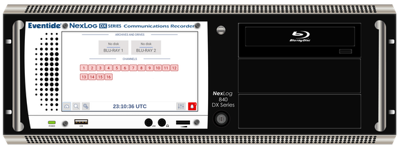
Fig. 2.9 NexLog 840 DX-Series™ Recorder with Touch Screen
The NexLog 840 DX-Series™ Recorder uses a horizontal hinge at the bottom of the unit. Loosening the thumb screw on the front will allow then entire front face to fold down for hard drive access.
The standard NexLog 840 DX-Series™ Recorder configuration use a touch screen display for control and doesn’t require a mouse or keyboard. All functions can be accessed from this interface. When necessary, an alphanumeric keyboard appears on the screen so that data such as channel names can be entered.
Systems without a touch screen display require that a monitor, keyboard, and mouse be plugged in for local configuration (setting of the IP address). Note that once basic networking setup is completed, it is possible to access all other configuration settings remotely via a web browser.
The RAID disk array (up to 16 TB of storage) can be accessed and disks can be replaced while the recorder is operating by opening the monitor door (hot-swap hard drive option required). One Blu-Ray multi-drive is standard for archiving on the NexLog 840 DX-Series™ Recorder.
Audio monitoring/playback is accomplished with an integral amplifier/speaker unit (left) with headphone jack, line-level output, and volume control below the LCD screen.

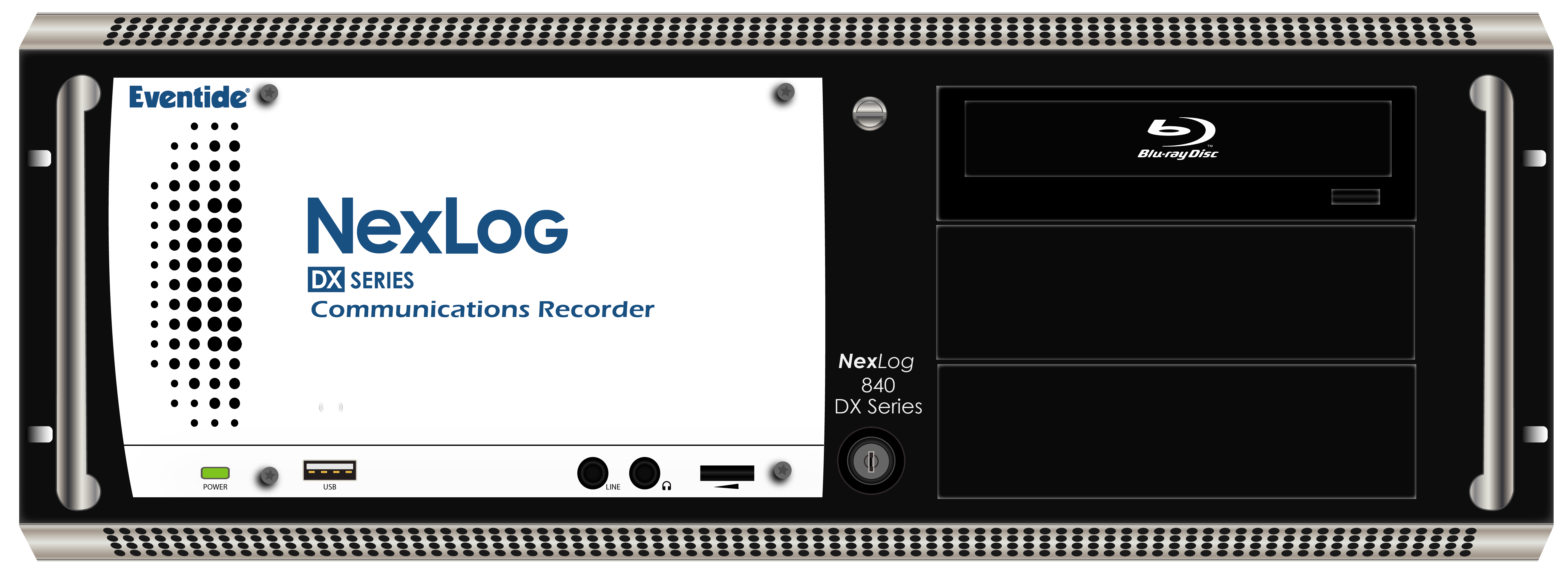
Fig. 2.10 Touch Screen (Close-Up)
The NexLog 840 DX-Series™ Recorder uses a keyed power switch on the front of the unit. Turn the key counter-clockwise to engage it. Holding the key in this position for more than 8 seconds, will forcefully power off the unit. Note: Avoid using the switch to power down the unit. Use it to power up only.

Fig. 2.11 Front Panel Audio Ports and Volume (Close-Up)
The audio section provides a 1/8-inch headphone jack and a 1/8-inch constant level Line Out jack for convenient re-recording. The volume control adjusts speaker and headphone volume.
2.2.2. Rear Panel

Fig. 2.12 Typical NexLog 740 DX-Series™ Recorder Rear Panel
The rear panel of this NexLog 740 DX-Series™ Recorder shows (from left to right): Dual Hot-Swap power supplies, two RS-232 ports for serial ANI/ALI and SMDR feeds or serial time sync, connector panel for PS/2 mouse and keyboard, two USB 2.0 ports, HDMI, VGA, DVI, two Ethernet ports, four USB 3.0 ports, and audio in/out (unused- use the front audio connectors instead). On the right side of the unit are spaces for five telephony boards, 2 (second from far left) through 6. Slot one is reserved for the optional hardware RAID controller. The sixth and seventh slots are reserved for PCI(e) add-on boards, one of which can be used for recording. You can see these clearly labeled below in a numbered illustration. Each board slot is labeled with its number , which is left to right when looking at them from behind the NexLog 740 DX-Series™ Recorder.
The redundant power supplies have an alarm that will sound when power is disconnected from either supply, whether from being unplugged or from a hardware failure. To acknowledge this alarm and silence it, press the small red button at the left-most edge of the back panel. It is labeled 7 in the diagram below.
The larger red switch, labeled 8, is the breaker reset. If someone plugs in an incompatible power supply, the breaker will trip, cutting all power to prevent electrical damage. After the power supply is replaced, press this switch to reset the breaker and restore power to the system.

1 - Power Module 1 | 14 - Serial Port 2 1 |
2 - Power Module 2 | 15 - RAID Controller (optional) |
3 - Power Plug 1 (NEMA 5-15P) | 16 - Microphone In Jack (unused) |
4 - Power Plug 2 (NEMA 5-15P) | 17 - Line In Jack (unused) |
5 - Power Switch 1 | 18 - Line Audio Out 2 |
6 - Power Status Light 1 | 19 - Audio Out To Front Panel 2 |
7 - Power Switch 2 | 20 - Sub Audio Output (unused) |
8 - Power Status Light 2 | 21 - Audio Pass Through To Front Panel |
9 - Power Alarm Reset Button | 22 - USB 3.1 Ports |
10 - Add-On Network Card (optional) | 23 - Ethernet Port 0 |
11 - Digital Recording Card (optional) | 24 - Ethernet Port 1 |
12 - Analog Recording Card (optional) | 25 - HDMI Output |
13 - Serial Port 1 1 |
- 1(1,2)
The serial ports are standard RS232 DB 9 ports.
- 2(1,2)
Line Out Jack will provide alarm audio on left channel and playback on right channel.
2.2.3. Operating Limits
Parameter | Range or Limits |
|---|---|
Voltage | 100 - 240VAC |
Frequency | 50 - 60 Hz |
Power (typical/max) | NexLog 740 DX-Series™ Recorder 200W/350W, NexLog 840 DX-Series™ Recorder 200W/400W |
Temperature | Operating +5C (41F) to 40C (104F) |
Humidity | 10% - 80% relative, non-condensing |
Altitude | -2,000 to +2,000 feet operating (to 22,000 feet non-operating). If operated at high altitudes, take special care that airflow is unrestricted by dust or obstacles. |
Vibration (Hard Disk Drives) | These units contain hard disk drive storage units and mechanical components that are sensitive to mechanical vibration. They are intended for operation in fixed locations. Typical vibration limits for the hard disk drives are as follows: Operating: .2 G, 5-300 Hz Non-Operating: 1 G, 5-300 Hz Note: There is a variant of the NexLog DX-Series™ available for high vibration environments, which adheres to MIL-STD-167-1A (25 Hz) |
Shock (Hard Disk Drives) | Typical shock limits for the hard disk drives are as follows: Operating: 1 G, 11 ms half-sine Non-Operating: 40 G, 11 ms half-sine Note: There is a variant of the NexLog DX-Series™ available, that has passed MIL-S-901D medium weight, Grade “B shock testing. |
Orientation | The archive drives are very sensitive to orientation. The recorder should always be mounted on a flat, non-sloping surface. |