2. Smart Edge Capture Device™ Setup
2.1. Unpacking the Smart Edge Capture Device™
Caution
Use care and assistance when lifting and handling the Smart Edge Capture Device™.
Check the box for damage. A crushed box, holes, or water damage, for example, could indicate that the Smart Edge Capture Device™ has been damaged. Open the box and inspect the Smart Edge Capture Device™ and associated accessories. If the equipment appears damaged contact Eventide right away and save the damaged box and packaging!
Check that the unit is delivered with the expected configuration and accessories. The packing slip states the contents. In addition, the box will include:
One power line cord per power supply module
One server software DVD disk labeled “Eventide Smart Edge Capture Device™ Software”
A disk with this manual and other documents.
Other accessories may be included, depending on your order.
2.2. Smart Edge Capture Device™ General Specifications
Smart Edge Capture Device™ | |
|---|---|
Product view |
|
Remote software | Web browser based Smart Edge Capture Device™ Configuration Manager |
Operating System | Linux (embedded) |
Call Record Database | Internal relational database with programmable retention |
Channel Inputs | Compression Rates (Kbits/s): 13.3, 16, 32, 64 Mu-law Frequency Response: 200 to 3400 Hz Signal to Noise: -50dB Crosstalk: -60dB AGC: 24dB Boost Impedance: >10 K ohm |
Network | Ethernet 1,000 Mbps (Qty. 2) |
Height | 1.75 inches (1 rack units) |
Depth | 14 inches |
Power | 350 watts |
Power supplies | Single Fixed |
Weight | 10.5 lbs (4.8 kg) |
Analog channels | 8-24 |
Digital PBX channels | 8-24 |
T1/E1/ISDN PRI channels | 24-60 |
VoIP channels | 8-40 |
Standard hard disk storage | 128GB SSD |
2.2.1. Rear Panel Details:

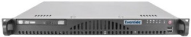
Fig. 2.1 Typical Smart Edge Capture Device™ Rear Panel
The rear panel of this Smart Edge Capture Device™ shows (from left to right): power supply, a RS-232 port for serial ANI/ALI and SMDR feeds or serial time sync, two USB 2.0 ports, two USB 3.0 ports, VGA and one slot for a telephony board.

Fig. 2.2 Diagram of Smart Edge Capture Device™ Rear Panel
1 - Power Module | 6 - Ethernet Device 1 (Eth0) |
2 - Power Plug (NEMA 5-15P) | 7 - Ethernet Device 2 (Eth1) |
3 - Serial Port 1 1 | 8 - VGA Output |
4 - USB 2.0 Ports | 9 - Diagnostic Port (not used) |
5 - USB 3.0 Ports | 10 - Add-on Telephony Board Slot (optional) |
- 1
The serial port is a standard RS232 DB 9 port.
2.3. Bench Test
Before installing the unit, you may want to run a brief bench test, especially if you are unfamiliar with Eventide Smart Edge Capture Devices™. The following steps are a suggested bench test procedure, which you may modify as you wish. If you change settings, note the defaults first and set them back to the defaults after you complete the test.
Connect a Monitor, Keyboard, and a Mouse.
Plug in the provided line cords to the appropriate line voltage.
Unlock the door and press the power switch. The boot process will start and diagnostic messages will scroll by on the monitor.
After several minutes, the screen will show the Login page of Configuration Manager. Login with the default user/password which is Eventide and the serial number of this Smart Edge Capture Device™.
Navigate to the Recording Interface page to see the channels that the Smart Edge Capture Device™ recognizes as ready for recording. For example, if you ordered a 16-channel unit (whether analog-only, digital-only, or a combination), you should see 16 green steady indicators when you expand the board view on this page.
Likewise, for 24 channels, 32 channels, and so on. This is a good time to make sure you see the expected number of channels.
Look at the menu on the left of the display to view the pages of the Configuration Manager.
Choose System: Date & Time to configure the time, time zone and time sync source for this system. We recommend doing this before making any recordings.
Choose Networking: Network Interfaces to configure the IP address for this system. This will allow you to connect to and administrate the Smart Edge Capture Device™ remotely.
When you have finished viewing each screen, you can shut down the unit as follows:
Important! Do not force a shutdown by pulling the power plug or using the power switch. A forced shutdown can result in corrupted files and loss of data.
Select System.
Select Power Off.
Select the Shutdown button.
Enter a reason for the shutdown.
Answer *OK* to the prompt.
After the Smart Edge Capture Device™ completes its controlled shutdown procedures, the unit will automatically shut down.
2.4. Installation
2.4.1. General
Smart Edge Capture Devices™ are computer equipment. They have essentially the same requirements, both physical and electrical, as standard servers, and similar attention should be paid to their environment to assure long life and reliable operation. Site preparation, especially for larger installations, may include providing rack cabinets and concentrating communication wiring – phone lines, radio, etc. – nearby.
2.4.2. Operating Limits
The installation should allow the units to operate within their electrical and physical operational limits.
Parameter | Range or Limits |
|---|---|
Voltage | 100 - 240VAC |
Frequency | 50 - 60 Hz |
Power (typical/max) | Smart Edge Capture Device™ 200W/350W |
Temperature | Operating +5C (41F) to 40C (104F) |
Humidity | 10% - 80% relative, non-condensing |
Altitude | -10,000 to +10,000 feet operating (to 22,000 feet non-operating). If operated at high altitudes, take special care that airflow is unrestricted by dust or obstacles. |
Vibration (Hard Disk Drives) | These units contain hard disk drive storage units and mechanical components that are sensitive to mechanical vibration. They are intended for operation in fixed locations. Typical vibration limits for the hard disk drives are as follows: Operating: .2 G, 5-300 Hz Non-Operating: 1 G, 5-300 Hz Note: There is a variant of the NexLog DX-Series™ available for high vibration environments, which adheres to MIL-STD-167-1A (25 Hz) |
Shock (Hard Disk Drives) | Typical shock limits for the hard disk drives are as follows: Operating: 1 G, 11 ms half-sine Non-Operating: 40 G, 11 ms half-sine Note: There is a variant of the NexLog DX-Series™ available, that has passed MIL-S-901D medium weight, Grade “B shock testing. |
Orientation | The Smart Edge Capture Device™ should always be mounted on a flat, non-sloping surface. |
2.4.3. Location Considerations
When choosing a location, consider the following:
Operating Limits. The location must respect the unit’s operating limits, as listed in the Operating Limits section of this manual.
Convenience. If the unit will be operated from its front panel, then it should be comfortably accessible to the operator. Service personnel should have access to the unit. If the unit is to be installed in a rack, special rack units that provide a horizontal writing surface are commercially available.
Security. If the unit must be physically secure, then it can be placed in a locked equipment room with limited access. This will also help ensure data security. Consider that a user with access to the unit can remove power, disconnect the input cables, monitor calls, and do other things to compromise your data. Logins are no protection against a determined attacker with physical access to a machine. In short, if you are concerned about malicious users making a purposeful effort to gain unauthorized access to your data, then the only real protection is to place the unit in a secure location.
Cable lengths. For analog signals, such as POTS lines and radio receiver outputs, cable lengths are not likely to be an issue. An adequate level can be obtained hundreds of feet from the signal source. The unit has programmable adjustments for low or high signal levels. That being said, shorter cable lengths will create less signal attenuation and pick-up less noise than longer cable lengths. For tapping digital PBX telephones and T1/E1 circuits, maximum cable lengths are extremely important, and can be different for different makes & models of telephone systems. Contact Eventide technical service for digital-tap cable length information for your particular digital phone system or T1/E1 circuits.
Particulates. The fans and hard drives, can be damaged by smoke and dust. If you find dust build up on the surfaces or the fans being clogged, consider changing the location.
Power dropouts or surges. The unit should be protected from power dropouts and surges. The chosen location should have line power available that is not on the same circuit as equipment that draws a large current on start-up, such as electric motors or compressors or banks of fluorescent lights. Line voltage fluctuations, brown-outs, and power outages can result in loss of data and damage to the unit. An Uninterruptible Power Supply is required to mitigate these problems. For a list of approved UPS units, see Connecting AC Power and UPS (Uninterruptible Power Supply).
Spilled liquids. Liquids spilled on the unit can damage it. The location should not encourage people to place coffee cups on the unit, for instance.
Vibration and Shock. Vibrating or physically shocking the unit while the hard drives are operating could damage the hard drives. The location should not be subject to vibration or jolting while the unit is operating.
2.4.4. Mounting Options
As normally provided, the unit can be mounted on any flat, non-sloping surface that can bear its weight. It can be rack mounted if the rack has a shelf to support it, and the supplied mounting ears can be attached to the rack with the rack screws provided, in order to prevent casual removal. The unit must not be mounted solely with the mounting ears and rack screws!
If no rack shelf is available, a rack-slide rail install kit, which includes slide rails, rear slide supports, brackets, and mounting hardware, can be ordered:
4-post Rack-Slide Rail Kit for the Smart Edge Capture Device™: Eventide Part# 324430
Alternatively, a center rack mounting option is also available:
2-post Center Rack Mount Kit for the Smart Edge Capture Device™: Eventide Part# 108109
2.4.5. Connecting AC Power and UPS (Uninterruptible Power Supply)
The Smart Edge Capture Device™ uses “universal” power supplies. All systems ship with US type power cords, end customer must provide a country appropriate power cord. This means you can plug the Smart Edge Capture Device™ into any line (mains) voltage from 100 volts to 240 volts nominal. However, to prevent unplanned shutdowns caused by power glitches or interruptions, Eventide strongly recommends the use of an Uninterruptible Power Supply (UPS) unit that meets certain minimum characteristics:
The UPS must provide power for a long enough period to allow orderly shutdown of the Smart Edge Capture Device™ in case of power failure.
If your facility has a backup generator, the UPS should provide power long enough to operate the Smart Edge Capture Device™ until the generator becomes operational following the start of a power failure (typically a minute or less) PLUS a period long enough to allow orderly shutdown of the Smart Edge Capture Device™ in case of generator failure.
The UPS should be an approved model, i.e., one that can communicate its status to the Smart Edge Capture Device™. This isn’t strictly necessary if your facility is manned and personnel are trained to shut down the Smart Edge Capture Device™ using the appropriate procedure in case of power failure before the UPS battery drains. However, an approved UPS will keep the Smart Edge Capture Device™ running and automatically signal to the Smart Edge Capture Device™ to perform a safe shutdown when its battery power gets low.
Eventide offers commercial-grade, heavy-duty rack-mount UPS units. Eventide has tested the following units and confirms they work with the Smart Edge Capture Devices™.
Manufacturer | Rating | Rack Height |
|---|---|---|
APC / Tripp-Lite | 1500VA, 940W, 120V | 2U (3-1/2 inch) |
APC / Tripp-Lite | 1500VA, 940W, 240V | 2U |
APC / Tripp-Lite | 750VA, 120V | 2U |
APC / Tripp-Lite | 750VA, 240V | 2U |
APC / Tripp-Lite | 3000VA, 2700W, 120V | 2U |
APC / Tripp-Lite | 3000VA, 2700W, 240V | 2U |
In addition, consumer-grade UPS units may be available locally and are suitable for more casual installations and shorter run-times. Eventide has tested the following units and confirms that they work with the Smart Edge Capture Devices™.
Manufacturer | Model | Recommended for |
|---|---|---|
APC | Back-UPS ES 500 | Smart Edge Capture Device™ |
To connect your Smart Edge Capture Device™ to a UPS, simply plug the UPS into an AC socket, and plug the Smart Edge Capture Device™ into the UPS using the power cords provided. If you use an approved UPS, also connect the UPS to one of the USB ports on the rear panel of the Smart Edge Capture Device™ using the cable provided with the UPS. This communication link will perform a safe shutdown when necessary, and also allow the Smart Edge Capture Device™ to notify you (by display and optionally by email) if there is a power problem.
Caution
The power cord is used to connect the Smart Edge Capture Device™ to main power. Remove power cord before servicing the unit.
2.4.6. Before You Connect Audio Signals to the Smart Edge Capture Device™
Before you connect the telephone lines, radio outputs, or other signals to be tapped and recorded, set the internal clock, date, time zone, and channel names on the Smart Edge Capture Device™. If you are installing (not upgrading) new software on a currently operating Smart Edge Capture Device™, disconnect the audio inputs until you have restored the configuration of the Smart Edge Capture Device™, including channel selection and time zone. The reason for this is that the Smart Edge Capture Device™ will begin recording as soon as it detects an input signal. Calls with the wrong time, date, and time zone may get recorded and will likely remain on the Smart Edge Capture Device™ for a long time. This might be confusing later when you search, filter, and archive calls. Refer to Section 3 of this document for configuration information including Date and Time settings.
2.4.7. Connecting Telephone, Radio, and Other Analog Audio Signals to the Smart Edge Capture Device™
This section applies to units equipped with an Analog Input Board. If you are not sure this board is installed, check the printed back-panel diagram that was packed with your Smart Edge Capture Device™.
Warning
To reduce the risk of fire, use only 26 AWG or larger telecommunication wire.
The Analog Input Board handles interfacing to analog audio signals. The number of channels per board will vary depending on which is ordered. Eventide sells 8, 16, and 24 channels versions of the Analog Board.
A mating connector is provided for each board unless a Quick Install Kit has been ordered (see The Optional Quick Install Kit). The connector has two rows of contacts. One row is numbered 1 through 25, and the other row is numbered 26 through 50. Numbering is such that pin 1 is opposite 26, and 25 is opposite 50. Each audio input requires two wires, in what is known as a “balanced” configuration. There is no “ground” connection. The channel and connector pin correspondence is detailed in *Appendix D: Channel Wiring for Eventide Analog Input Boards* of the NexLog DX-Series User Manual.
To connect a telephone line to a given channel, simply connect the two wires to the two pins for that channel. It is not necessary to check or observe polarity.
To connect an audio source such as the line output or recording output of a radio, connect the “hot” lead to one pin and the ground or shield lead to the other. Again, there is no distinction between input pins. Either can be connected to the “hot” lead.
Any audio source may be connected, provided that the audio voltage is nominally in the .1 - 1 Volt range and remains fairly constant. Differing voltage levels are compensated for when setting up the board parameters in the configuration manager. Not recommended are sources with greatly varying levels, such as “speaker” outputs. Also unusable are “microphone” signals, whose levels are too low by far to be usable without pre-amplification.
2.4.7.1. The Optional Quick Install Kit
For any analog telephone recording board in the Smart Edge Capture Device™, you will have received either a mating blue-ribbon connector, or if ordered as an option, a Quick Install Kit. The connections for the mating blue-ribbon connector are detailed in *Appendix D: Channel Wiring for Eventide Analog Input Boards*. The pins are numbered on the connector itself for reference.
The Quick Install Kit, Eventide part #109033-003 (3-meter cable) and #109033-007 (7-meter cable), include the following components:
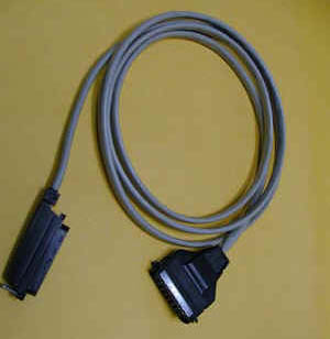
Figure 10—Quick Install Kit Components
| Cable Connects the Smart Edge Capture Device™ telephony board to the punch block. The rear-entry connector (right in photo) goes to the Smart Edge Capture Device™ and is fastened to the telephony board rear panel with small wire bails on each side. The end-entry (left in photo) RJ‑21 male connector goes to the punch block and is held in place with a Velcro strip. Note: This cable may have special wiring! Before substituting a standard 50-pair extender cable for this cable, confirm that the telephony boards in your Smart Edge Capture Device™ do not have special connections. (See Channel Wiring for Analog Input Boards). If you need a greater length, you may use an extender cable in series with the cable provided as part of the kit whether or not it is one with special wiring. |
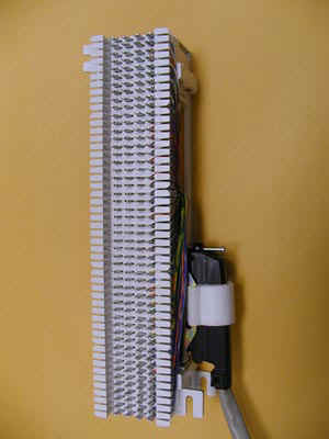
| Punch Block The punch block is a convenient, industry-standard appliance used to connect twisted pair telephone wiring to the Smart Edge Capture Device™. It provides a central location to connect your physical wiring. The 25-pair “Split 50” 66 Block has 50 rows and four columns. Each row contains four connectors (contacts). Each outside contact contains an electrical connection to the one next to it, creating a pair of contacts, but the left pair of contacts are electrically isolated from the right pair of contacts (thus, they are “split”). Using a punch-down tool (not provided), the telephone wires are forced into a slit cut in the contacts in the block, which makes a firm electrical and physical connection. The blocks are usually mounted in the orientation shown. The right side of the block has a female RJ‑21 connector for the cable that goes to the Smart Edge Capture Device™. The left side of the punch block (opposite the RJ‑21 connector) is used to connect the telephone (or other audio) lines. |
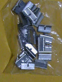
| Bridging Clips The right side (nearest the connector) has each column connected to an associated connector pin-pair so that the top row is connected to pin 1, the next row to pin 26, the third to pin 2, etc. Thus, adjacent vertical rows form one signal pair. When you connect the first telephone line, you just start at the top and connect the wire pair to the first two rows on the left. The next wire pair would go to the next two rows down, on the left. Finally, to connect the telephone line to its associated Smart Edge Capture Device™ input, slip two bridging clips over the two center contacts in each row. |
The purpose of the punch block system is to centralize your connections, as well as to provide a clean way to isolate the telephone or radio system from the Smart Edge Capture Device™, should it become necessary. The components can be isolated by removing clips, rather than removing wires.
2.4.8. Connecting Digital PBX Stations that are to be Tapped
Note: For tapping digital PBX telephones and T1/E1 circuits, maximum cable lengths are extremely important, and can be different for different makes & models of telephone systems. Contact Eventide technical support for digital-tap cable length information for your particular digital phone system or T1/E1 circuits.
This section applies to units equipped with one or more Digital PBX Station tapping Boards. If you are not sure this board is installed, check the printed back-panel diagram that was packed with your Smart Edge Capture Device™.
Warning
To reduce the risk of fire, use only 26 AWG or larger telecommunication wire.
The Digital PBX Station tapping Board handle interfacing to certain Digital PBX Station makes and models (check with Eventide for compatibility). The number of channels per board will vary depending on which is ordered. Eventide sells 8, 16, and 24 channels versions of the Digital PBX Station tapping Board.
A mating connector is provided for each board unless a Quick Install Kit has been ordered (see The Optional Quick Install Kit). The connector has two rows of contacts. One row is numbered 1 through 25, and the other row is numbered 26 through 50. Numbering is such that pin 1 is opposite 26, and 25 is opposite 50. For most Digital PBX systems (except Mitel Supersets, Avaya Index phones, and ROLMphones), each Digital PBX Station requires two wires.
To connect a supported digital PBX telephone line to a given channel, connect the two wires to the two pins for that channel.
2.4.9. Connecting to an Ethernet Network
Connect to an Ethernet network by attaching a network cable between the RJ45 jack on the back of the Smart Edge Capture Device™ and your hub, switch or router. The cable should be CAT5 or equivalent with a male RJ45 plug for the Smart Edge Capture Device™ end and with the connector pin wiring going straight through from end to end. Alternatively, a crossover cable can be used to isolate the Smart Edge Capture Device™ from the network and connect directly to a PC’s network connection without using a router or switch. The Smart Edge Capture Device™ has two RJ45 jacks and can be connected to multiple networks simultaneously. The jack closest to the input boards is Device 2 (eth1), and the jack to its left is Device 1 (eth0). The third jack, close to the power supplies, is not used.
2.4.10. Connecting a Keyboard
A keyboard can be connected to a Smart Edge Capture Device™ to allow easier and faster data entry and interaction than is permitted by the Smart Edge Capture Device™’s optional front panel interface. This can be useful for performing system administration tasks from the front panel and for diagnostic work.
Note
The same configuration capabilities that are available by connecting a monitor and keyboard can be accessed via a web browser from a PC, using the browser-based Smart Edge Capture Device™ Configuration Manager. Under most circumstances this will allow for a quicker setup procedure.
Connect a USB keyboard to any USB connector on the Smart Edge Capture Device™. This may be done while the Smart Edge Capture Device™ is running and does not require a shutdown and restart of the Smart Edge Capture Device™.