6.5. Cisco CallManager Built-in-Bridge
6.5.1. Built-in-Bridge Introduction
The purpose of this document is to describe the steps to ensure a successful integration between an Eventide NexLog DX-Series Logging recorder and Cisco Call Manager using Built in Bridge (BIB) for recording.
Built in Bridge, which Cisco defines as using the IP Phone’s internal DSP resources, not a SPAN of the Ethernet switch port, instead it uses a SIP trunk to record a duplicate stream of audio from the recorded phones via the phones own built in ‘bridge’. Following is a Cisco Diagram of the connectivity.
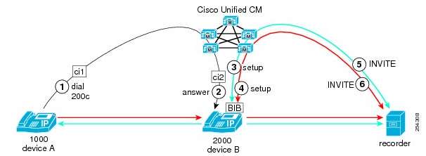
Fig. 6.62 Cisco Built-in-Bridge Diagram
Eventide supports Automatic Call Recording mode (without CTI), in this mode calls are delivered to the Eventide recorder of the previously mentioned SIP Trunk.
Configuring the Cisco Unified Call Manager for recording via the phones BIB is outside the scope of this document. However, the high level steps required are as follows:
Ensure the Cisco Phones you want to record support the recording feature
Create SIP profile for the Eventide recorder
Create SIP trunk security profile
Create SIP trunk that points to the Eventide recorder
Create recording profile
Create a route pattern for the Eventide recorder
Enable Built-in-Bridge on all phones to be recorded
Configure tones for recording
Set the Codec configuration, Eventide supports G.711, G.722 by default and G.729a/b with optional licensing.
Once the Cisco Unified Call Manager is configured appropriately, there will be corresponding information that needs to be entered into the “SIP Trunk (SPAN, Endpoint, or Cisco BIB)” template in the NexLog DX-Series Web Configuration Manager.
6.5.2. NexLog DX-Series Configuration Overview
Each of the following steps will be explained or shown with screen shots:
Confirm NexLog DX-Series version and licensing
Configure one of the NexLog DX-Series physical Network Interface Cards to a free IP address
Add a virtual recording interface board
Select the number of VoIP channels and “Cisco CallManager Built-in-Bridge” Recording Template
Fill in the required fields
Save the template
Verify recording
Note
Where data entry is required, the “Typical Source” to ascertain the data from is noted.
6.5.3. Cisco Unified Call Manager Built-in-Bridge Configuration Detail
6.5.3.1. NexLog DX-Series firmware version and Licensing
Ensure that the NexLog DX-Series is licensed appropriately for VOIP/RTP VoIP Channels. VoIP recording is licensed in groups of 8 channels, this example system has 32 channels. If proper licenses are not present contact Eventide technical support before proceeding.
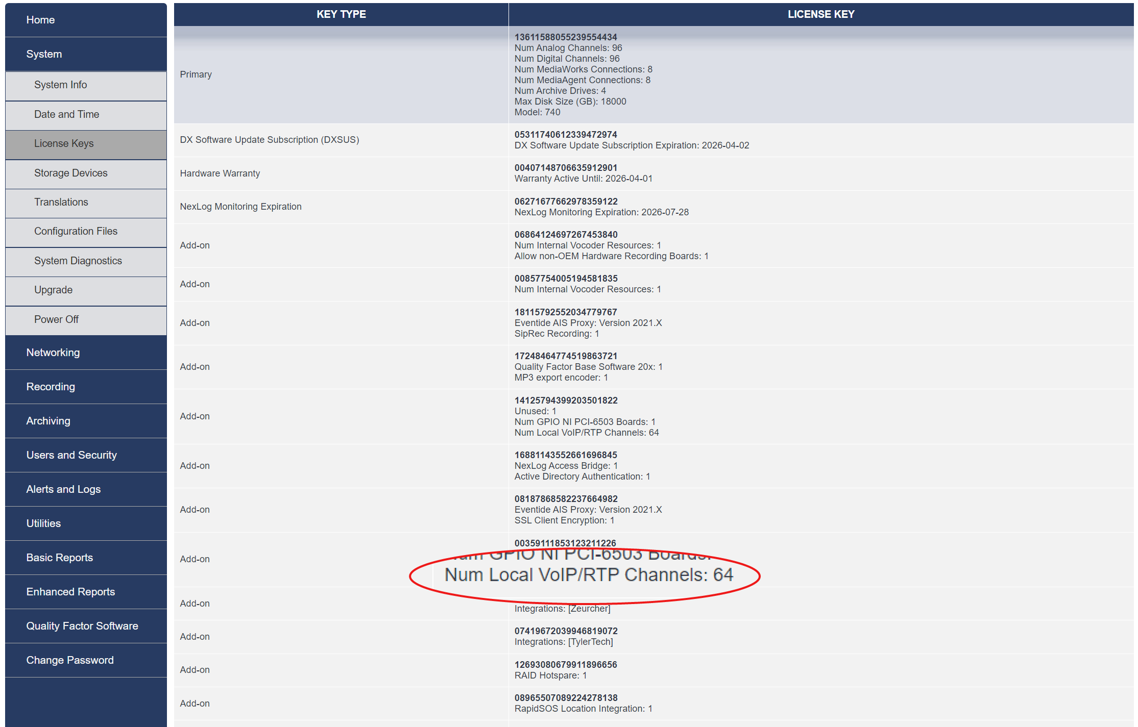
Fig. 6.63 VOIP License
6.5.3.2. Configure physical Network Interface Card
Connect a straight through network cable from the corresponding Network Interface Card on the Eventide recorder to a switch port that will have access to the network that the phones reside on.
On the network interfaces menu, select one of the currently unused Network Interface devices and Select “Type” Static. DHCP is supported, but not recommended because if the IP address changes, the new IP address will need to be entered into other configuration screens. Enter appropriate Netmask, Gateway and Broadcast addresses for the network.
Save the template.
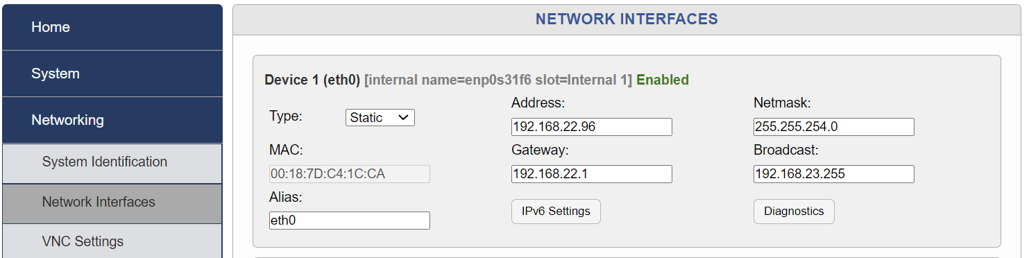
Fig. 6.64 Network Interface
6.5.3.3. Select “Cisco CallManager Built-in-Bridge” Template and Number of Channels
In order to add the Cisco CallManager Built-in-Bridge Template, Navigate to Recording > Recording Interfaces > Add Virtual Recording Interface
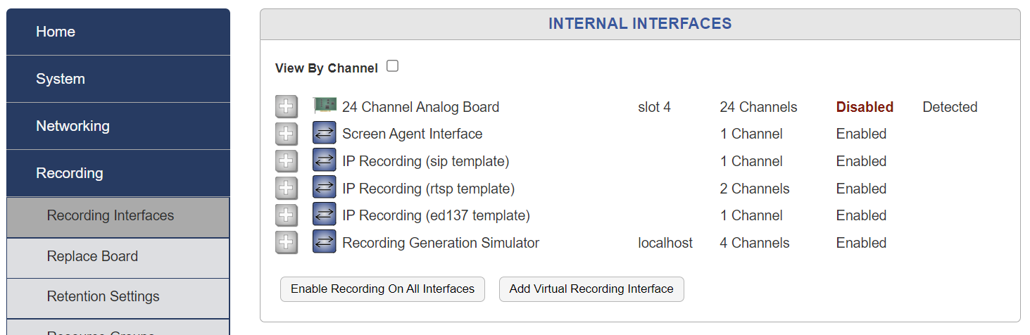
Fig. 6.65 Add Interface
Select Cisco CallManager Built-in-Bridge and note that the number of IP channels selected is the maximum number of simultaneous calls that can be recorded at one time. The NexLog DX-Series must be licensed for at least this number of VoIP Channels.
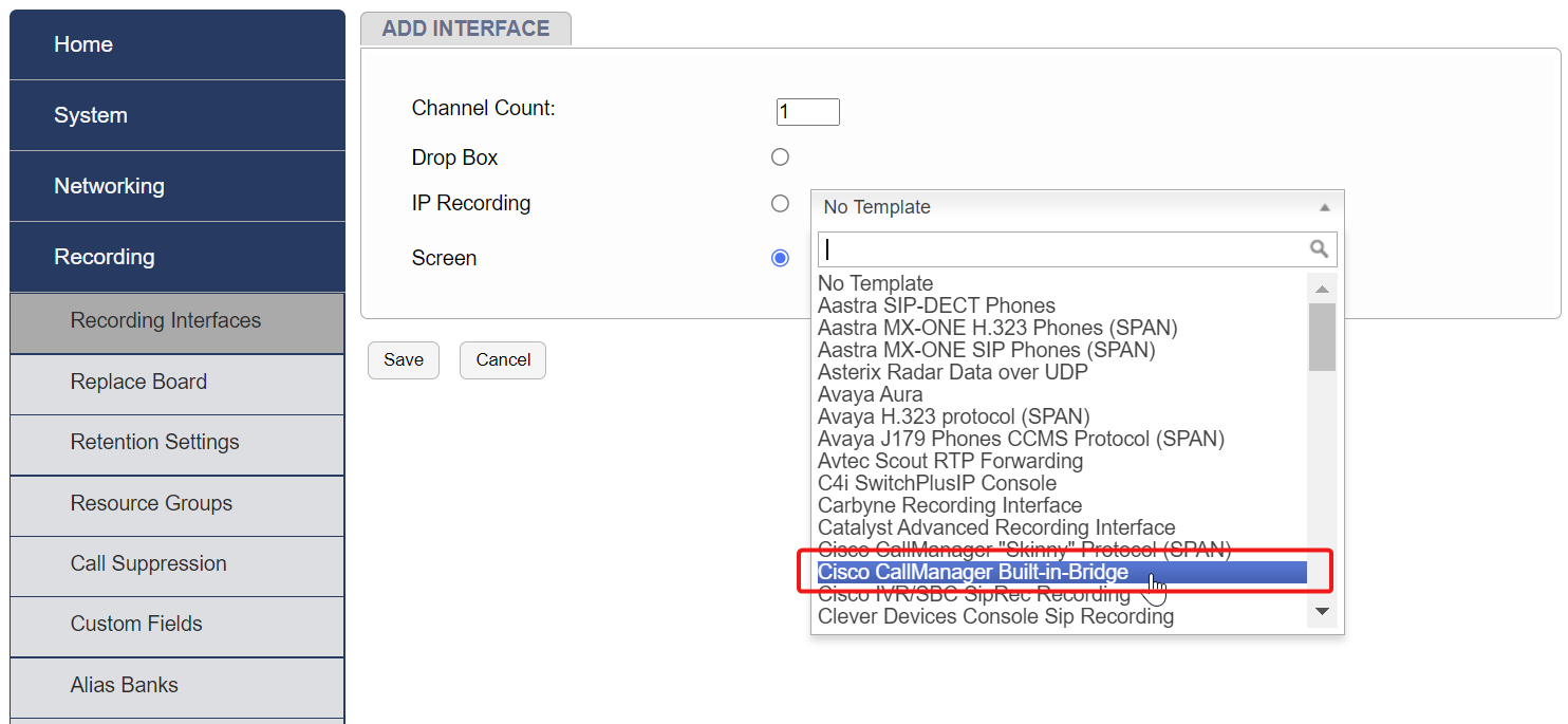
Fig. 6.66 Add BIB Interface
6.5.3.4. Fill in the “Cisco CallManager Built-in-Bridge” Template Fields
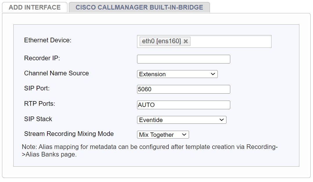
Fig. 6.67 Add BIB Interface Configurations
Template Field Detail
Ethernet Device: Select the physical Ethernet/NIC of the NexLog DX-Series recorder which is used to receive the SIP trunk carrying the BIB calls.
Recorder IP: IP address of the Eventide recorders Network Interface Card
Channel Name Source: Choose which piece of metadata will be used to name the channel when recordings are stored.
Extension: Use extension of the phone being recorded.
Near End Device Identifier: Use the device name identifier as defined in the Cisco Call Manager.
SIP Port: Default is 5060 and should not be changed, unless otherwise instructed to do so.
RTP Ports: Default is 6000-7000, do not change, unless otherwise instructed to do so.
SIP Transport Protocol: Enter SIP over UDP or SIP over TCP as appropriate.
New in version 2024.1.
Field Mappings: This optional section allows the ability to map and extract more complex metadata fields to channel name display, e.g. MAC Address.
To add specific Field Mapping data, select Edit and populate all requested Metadata Field Name and SIP Field Taxonomy data. Once entered, Select Populate then Save.
Note
Multiple entries can be added.
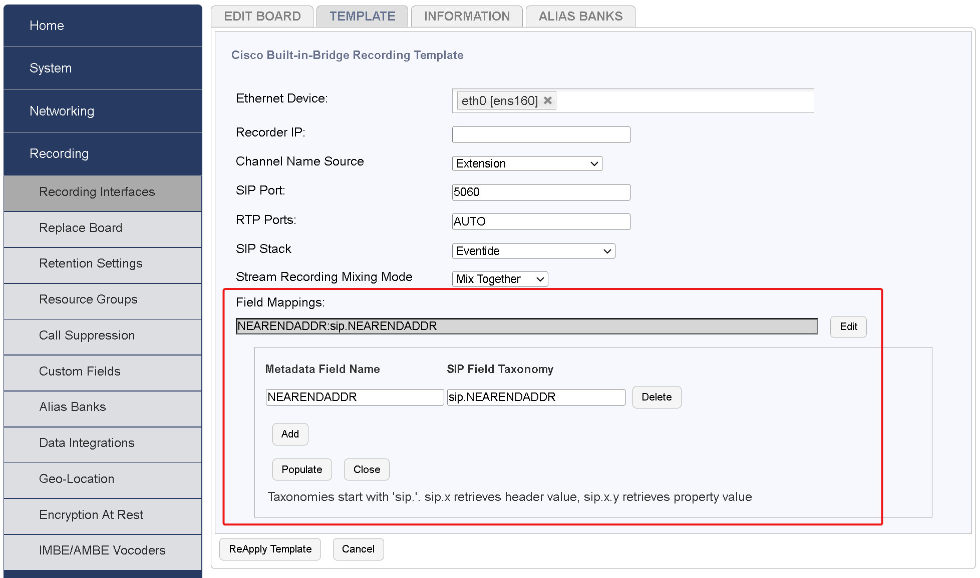
Fig. 6.68 Add BIB Field Mappings
These settings are also available by expanding the channel view and selecting the gear icon under the MORE tab.
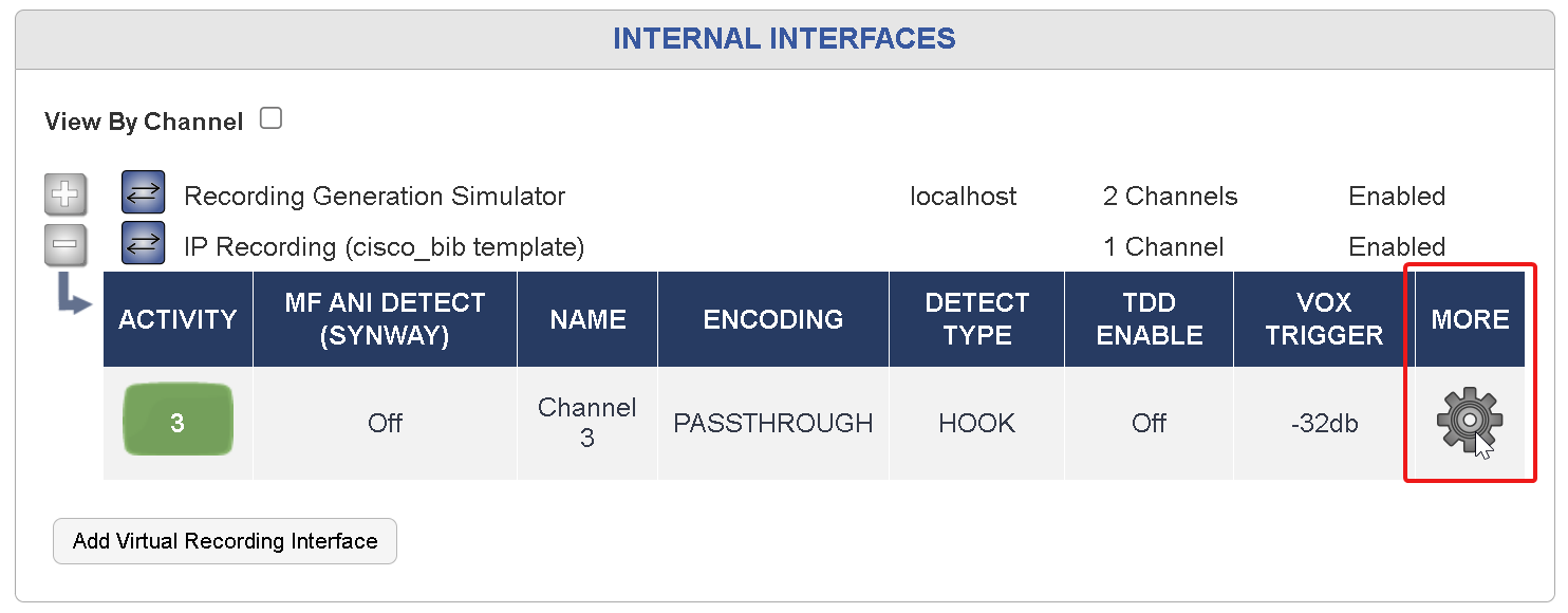
Fig. 6.69 Add BIB Field Mappings
The Field Mappings can be added under the RTP tab in the Metadata Settings.
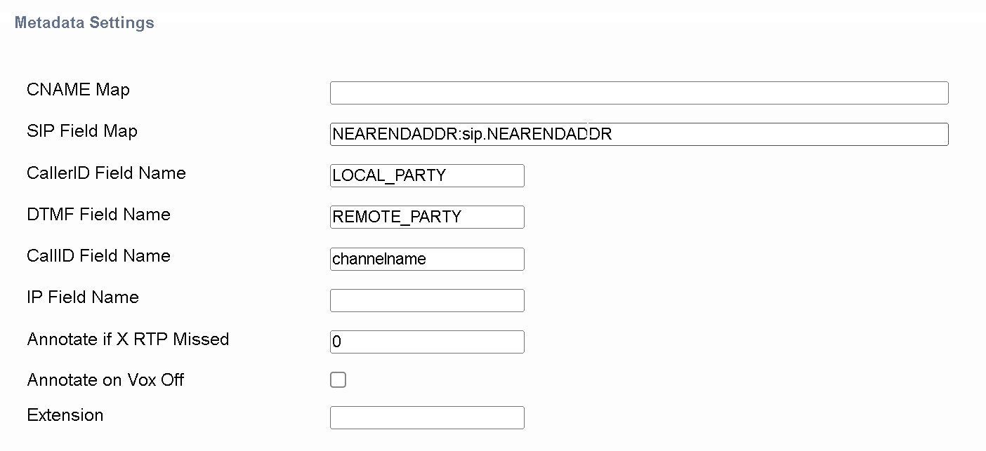
Fig. 6.70 Add BIB Field Mappings
6.5.3.5. Save The Template
After filling in all the fields, click Save. The NexLog DX-Series is ready to record.
6.5.3.6. Verify Recording
Place a series of test calls between phones inside and outside calls. Use MediaWorks DX or the front panel display to verify recording of all test calls.
6.5.3.7. Troubleshooting
SYMPTOM | Possible Causes/Solutions |
NexLog DX-Series Not Recording | Check IP connectivity between NexLog DX-Series and Network port |
MediaWorks DX does not play back P25 calls | Check IP Connectivity between NexLog DX-Series and local LAN |