6.12. MOTOTRBO Controller-less Recording Interface
6.12.1. MOTOTRBO Controller-less Recording Interface Introduction
The purpose of this document is to describe the steps to ensure successful integration between an Eventide NexLog740 or NexLog840 Logging recorder and MOTOTRBOTM Site Connect (IPSC), Capacity Plus (CPC) or Linked Capacity Plus (LCP) professional two-way radio system. The document assumes knowledge of the NexLog front panel interface and the browser-based configuration manager, it does not discuss recording interfaces beyond the MOTOTRBO integration. For more details on these interfaces, please refer to their respective manuals. This document also assumes knowledge of the Motorola Customer Programming Software (CPS) which is required to program the MOTOTRBO repeaters and site topology.
The NexLog will appear in the MOTOTRBO environment as a 3rd party application peer in any of the three radio system topologies. Therefore, the NexLog is required to have a unique Peer ID within the MOTOTRBO radio topology. The NexLog will also need to assume a set of appropriate parameters that are programmed into the MOTOTRBO Master Repeater. This is the overall purpose of the following Integration guide.
Required Personnel
Eventide dealer/reseller Technician
MOTOTRBO System Administrator/Technician
Customer LAN Network Administrator
IP Network Connectivity The NexLog ideally will be assigned an IP address within the same LAN as the MOTOTRBO master repeater and peer repeaters. If the NexLog is separated from the LAN where the MOTOTRBO repeaters reside, it will most likely be separated by a firewall. If the latter is the case, consult the Customer LAN Network administrator to configure the firewall to allow all IP traffic to flow bi-directionally between the NexLog IP address and the MOTOTRBO repeater IP address.
License Required
This feature must be licensed to be used. Contact your Eventide Communications Dealer for assistance.
6.12.2. Add Virtual Recording Interface
Select the number of IP channels/number of talk paths
Select the “MOTOTRBO Recording Interface” Template
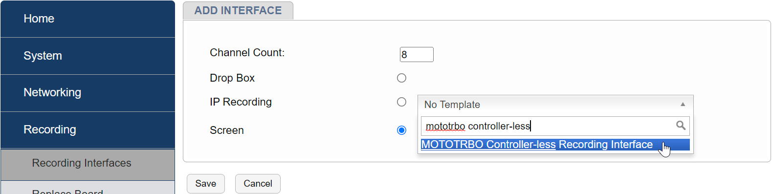
Fig. 6.87 Add Interface
Note
This is the maximum number of talk paths between the NexLog and the MOTOTRBO systems that can be recorded, and not to be confused with “Talk Groups”, multiple Talk Groups can be on one “Talk Path”.
6.12.2.1. Fill in MOTOTRBO Recording Interface Template Fields
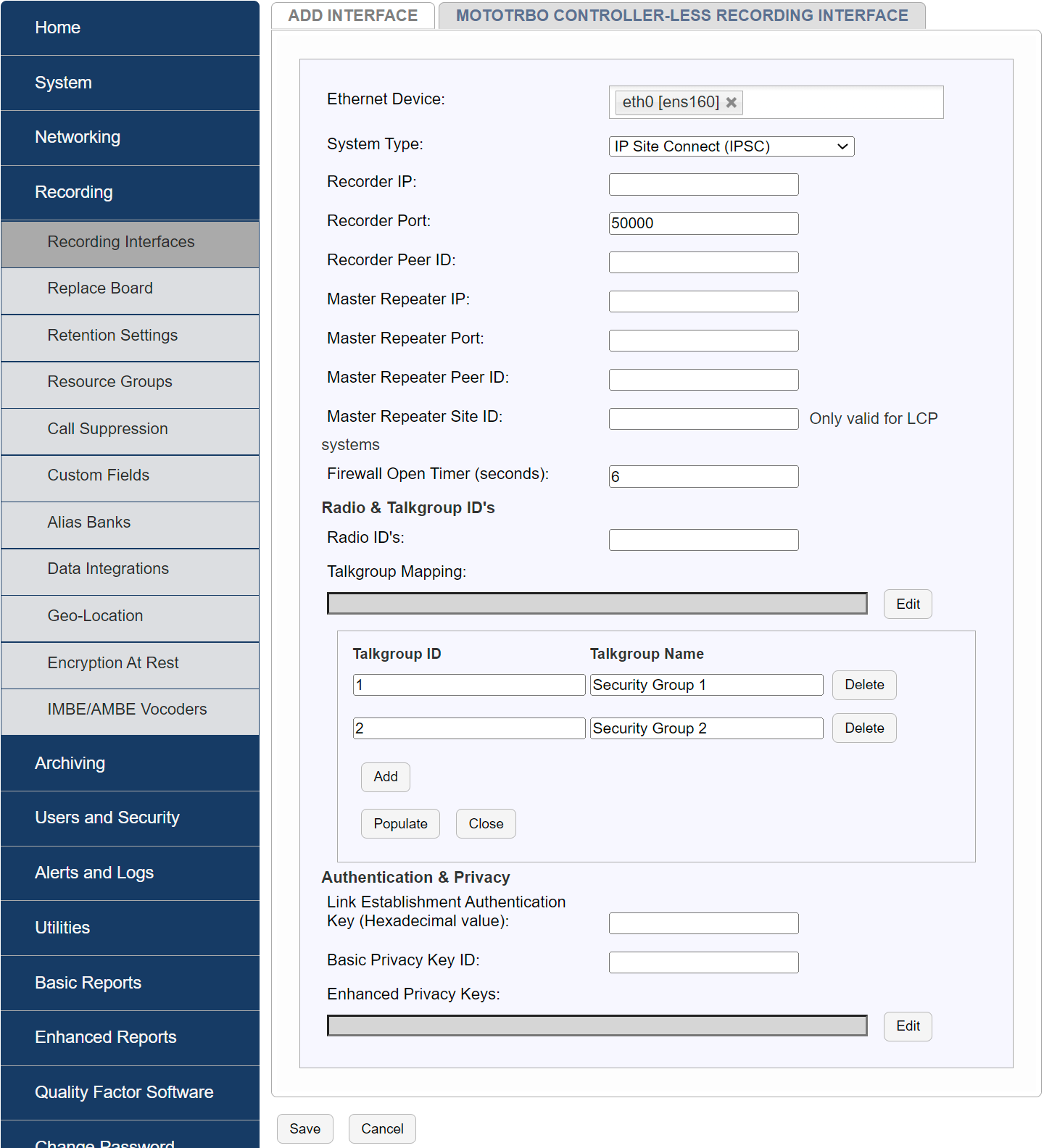
Fig. 6.88 Configure Interface
Select the MOTOTRBO “System Type”: There are three different types of MOTOTRBO systems supported by NexLog:
Site Connect (IPSC)
Capacity Plus (CPC)
Linked Capacity Plus (LCP)
The data required for each system type is the same, except for Linked Capacity Plus (LCP), which requires one additional parameter, “Master Repeater Site ID”.
6.12.2.2. Network Administrator
Ethernet Device: Select the physical Ethernet/NIC of the NexLog recorder which is used to record MOTOTRBO radio transmissions and is physically connected to the same LAN as the MOTOTRBO Master Repeater
Typical Source: Customer Network Administrator
Recorder IP: IP address of the NexLog Ethernet/NIC selected above
Typical Source: Customer Network Administrator. Typical Source: Customer Network Administrator.
Note
The MOTOTRBO system employs a terminology where each repeater in the system is considered a “Peer” and each repeater has a unique Peer ID. The NexLog recorder appears to the MOTOTRBO system as 3rd party application peer
Select the MOTOTRBO “System Type”: There are three different types of MOTOTRBO systems supported by NexLog:
Site Connect (IPSC)
Capacity Plus (CPC)
Linked Capacity Plus (LCP)
The data required for each system type is the same, except for Linked Capacity Plus (LCP), which requires one additional parameter, “Master Repeater Site ID”.
Recorder Port: UDP port that the NexLog recorder will use to record audio, default is 50000 and is typically not changed.
Typical Source: Eventide dealer/reseller Technician.
Recorder Peer ID: Unique ID (Decimal Integer) designated for the NexLog recorder in the MOTOTRBO system. I.e. The NexLog is treated as 3rd party application peer.
Typical Source: MOTOTRBO System Administrator/Technician.
Master Repeater IP: IP address of the MOTOTRBO Master Repeater.
Typical Source: Customer Network Administrator.
Master Repeater Port: UDP port used by the MOTOTRBO Master Repeater.
Typical Source: MOTOTRBO System Administrator/Technician.
vMaster Repeater Peer ID:** Unique ID (Decimal Integer) of the MOTOTRBO Master Repeater in the environment.
Typical Source: MOTOTRBO System Administrator/Technician.
Master Repeater Site ID (applicable only to Linked Capacity Plus (LCP) environments): Unique ID (Decimal Integer) of the location/site where the MOTOTRBO Master Repeater is located.
Typical Source: MOTOTRBO System Administrator/Technician.
Firewall Open Timer (seconds): Amount of seconds between ‘keep alive’ messages the recorder will send to retain membership in the MOTOTRBO peer group. Default is 6 seconds and not usually changed.
Typical Source: MOTOTRBO System Administrator/Technician.
Radio IDs: Comma separated list of radio IDs that will be recorded when making Radio to Radio (private) calls. Enter a value of zero “0” for all radio IDs. Range of IDs can also be entered (e.g. 5-10,100-150)
Typical Source: MOTOTRBO System Administrator/Technician.
Talk Group Mapping: Select “Edit” to create a relationship listed of mapping between the MOTOTRBO Talkgroup IDs and a more meaningful Talkgroup name that will be used by the NexLog for displaying the recorded channels. Multiple mappings can be created by clicking “Add”. Click “Populate” to fill in and complete the Talkgroup Mapping.
Typical Source: MOTOTRBO System Administrator/Technician.
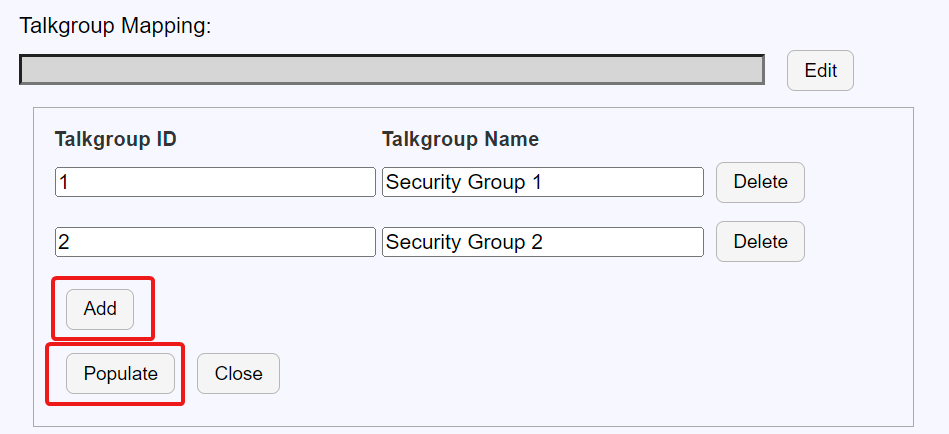
Fig. 6.89 Talk Group Mapping
Link Establishment Authentication Key: Hexadecimal value used to authorize link establishment, it is the same value on all repeaters and the NexLog. This is an optional security feature used in some MOTOTRBO environments. If this feature is not used, the field can be left blank.
Typical Source: MOTOTRBO System Administrator/Technician.
Basic Privacy Key ID: Integer value 1-255, used to identify privacy key, it is the same value on all repeaters and the NexLog.
Typical Source: MOTOTRBO System Administrator/Technician.
Enhanced Privacy Keys: Click “Edit” to create a relationship between Enhanced Privacy Key IDs and Key Values, multiple relationships can be added by clicking “Add”. Click “Populate” to fill in and complete the Key ID and Key-Value pairs.
Typical Source: MOTOTRBO System Administrator/Technician.
Save the template
After filling in all the fields, click Save. The NexLog will now attempt to contact the Master Repeater and establish itself as a 3rd party application peer in the MOTOTRBO environment.
6.12.2.3. Configure internal or external DVSIs
License Required
DVSI will require a “Num Internal Vocoder Resources” add-on license key. Contact your Eventide Communications Dealer for assistance.
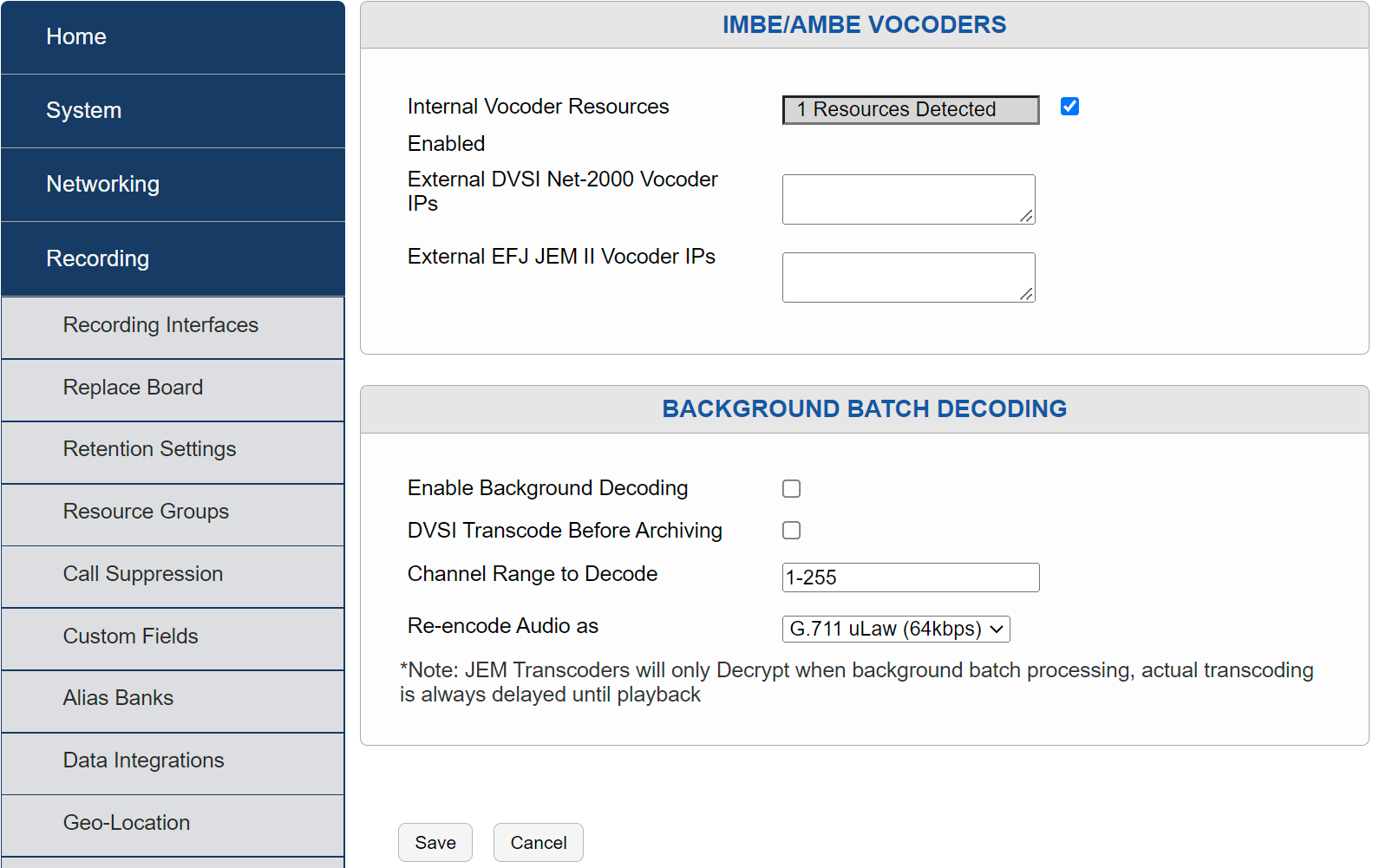
Fig. 6.90 IMBE/AMBE Vocoder Configuration
MBE Transcoder IP: This is the IP address of the DVSI brand decoder that is used to decode AMBE audio during playback.
Choose the appropriate next step based on the physical configuration of the DVSI vocoder. If the DVSI transcoder function is internal to the recorder, follow the “Configure Internal DVSI IMBE/AMBE Transcoder” step. If the DVSI is an external 2U device, follow the “Configure Multiple external IMBE/AMBE Transcoder IPs” step.
6.12.2.3.1. Configure Internal DVSI IMBE/AMBE Transcoder
If the DVSI IMBE/AMBE Transcoder is internal, the system will recognize the Vocoder. To use, select “Enable”
Fig. 6.91 IMBE/AMBE Vocoder Configuration
Note
There may be more than one in the environment to allow for higher amounts of simultaneous IMBE/AMBE transcoding for playback. If so, enter one of the IP addresses in this field, the remaining transcoders will be configured in the subsequent step.
6.12.2.4. Check for Alerts
Check the NexLog front panel and/or configuration manager for any system alerts or MOTOTRBO-specific alerts. There will be alerts specific to the MOTOTRBO integration if there are problems saving the template data.
6.12.2.5. Verify Recording
Place a series of test calls between radios on both encrypted and unencrypted talk groups. Use MediaWorks DX or the front panel display to verify successful recording of all test calls.