6.13. MOTOTRBO Capacity Max Recording Interface
6.13.1. MOTOTRBO Capacity Max Recording Interface Introduction
The purpose of this document is to describe the steps to ensure a successful integration between an Eventide NexLog740 or NexLog840 Logging recorder and MOTOTRBO CAPACITY MAX DMR two-way radio system. The document assumes knowledge of the NexLog browser-based configuration manager, it does not discuss recording interfaces beyond the CAPACITY MAX integration. For more details on these interfaces, please refer to their respective manuals. This document also assumes knowledge of CAPACITY MAX configuration and setup.
The NexLog will interface to the CAPACITY MAX system through the Voice and Radio Command (VRC) Gateway, referred to in this document as the VRC Gateway. Each VRC gateway can support up to 100 active talkpaths. Each CAPACITY MAX system supports up to 5 pairs of primary and backup VRC Gateways. The NexLog can support multiple pairs of redundant VRC Gateways by creating a separate recording template for each pair of redundant VRC Gateways. Creating the recording templates is discussed further in this document.
The VRC Gateway audio recording interface supports the delivery of the following types of calls to the NexLog recorder
Calls between Radios
Calls between Radios and Dispatch
Telephony Calls
Broadcast, Site/Multisite All Call
Emergency Voice Calls
Individual / Group Calls
Encrypted/ Clear Calls
Calls are recorded in AMBE+2 codec format, therefore, DVSI resources are required for playback. MediaWorks DX is used to search and replay calls. It will also indicate the types of calls, as well as Privacy level which is indicated by “CLEAR” or “ENHANCED”
6.13.2. NexLog Capacity Max Configuration Detail
Add Virtual Recording Interface
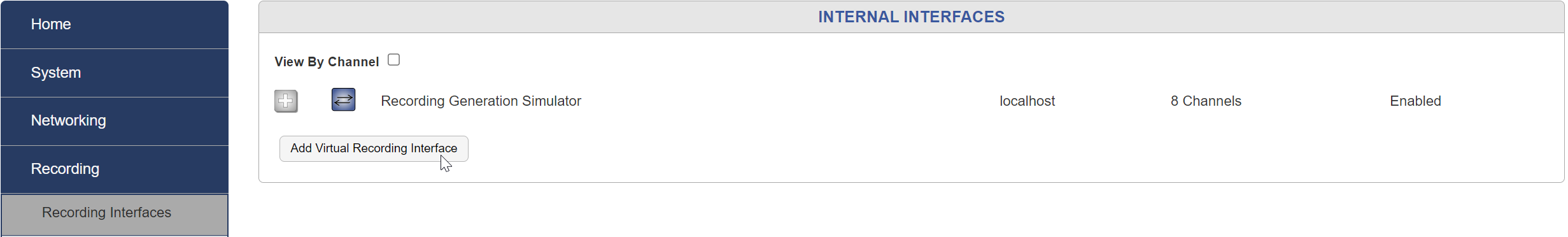
Fig. 6.92 Add Interface
Select the number of IP channels/number of talk paths and choose the “MOTOTRBO CAPACITY MAX Recording Interface” Template in the dropdown “Local IP” template section.
Note
This is the maximum number of talk paths between the NexLog and the CAPACITY MAX that can be recorded, and not to be confused with “Talk Groups”, multiple Talk Groups can be on one “Talk Path”.
6.13.2.1. Template Field Details
The following figure has the fields populated for illustrative purposes, the actual values in each installation will most likely be different. Verify each value with the CAPACITY MAX System Administrator/Technician or the Customer Network Administrator.
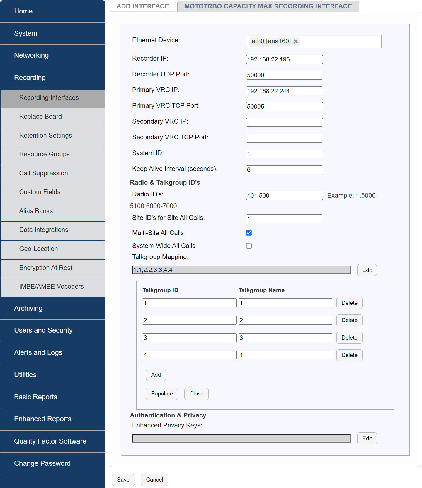
Fig. 6.93 Template Configuration
Ethernet Device: Select the physical Ethernet/NIC of the NexLog recorder which is used to record CAPACITY MAX radio transmissions and is physically connected to the same LAN as the CAPACITY MAX VRC Gateway
Typical Source: Customer Network Administrator
Recorder IP: IP address of the NexLog Ethernet/NIC selected above.
Typical Source: Customer Network Administrator
Recorder Port: UDP port that the NexLog recorder will use to record audio, default is 50000 and is typically not changed
Typical Source: Eventide dealer/reseller Technician
Primary VRC IP: IP address of the CAPACITY MAX VRC Gateway
Typical Source: CAPACITY MAX System Administrator/Technician
Primary VRC TCP Port: TCP port used by the VRC Gateway to send calls and data to the recorder
Typical Source: CAPACITY MAX System Administrator/Technician
Secondary VRC IP: IP address of the CAPACITY MAX VRC Gateway. Can be left blank if there is not a redundant VRC Gateway
Typical Source: CAPACITY MAX System Administrator/Technician
Secondary VRC TCP Port: TCP port used by the VRC Gateway to send calls and data to the recorder. Can be left blank if there is not a redundant VRC Gateway
Typical Source: CAPACITY MAX System Administrator/Technician
System ID: Unique ID (Decimal Integer) of the CAPACITY MAX VRC Gateway
Typical Source: CAPACITY MAX System Administrator/Technician
Keep Alive Interval (seconds): Amount of seconds between ‘keep alive’ messages the recorder will send to retain connection or determine failover to the Secondary VRC Gateway. Default is 6 seconds and not usually changed.
Typical Source: CAPACITY MAX System Administrator/Technician
Radio IDs: Comma separated list of radio IDs that will be recorded when making Radio to Radio (private) calls. Enter a value of zero “0” for all radio IDs, or a range of IDs can also be entered (e.g. 5-10,100-150)
Typical Source: CAPACITY MAX System Administrator/Technician
Talk Group Mapping: Click “Edit” to create a relationship listed of mapping between the CAPACITY MAX Talkgroup IDs and a more meaningful Talkgroup name that will be used by the NexLog for displaying the recorded channels. Multiple mappings can be created by clicking “Add”. Click “Populate” to fill in and complete the Talkgroup Mapping
Typical Source: CAPACITY MAX System Administrator/Technician
6.13.2.2. Authentication and Privacy
Enhanced Privacy Keys: Click “Edit” to create a relationship between Enhanced Privacy Key IDs and Key Values, multiple relationships can be added by clicking “Add”. Click “Populate” to fill in and complete the Key ID and Key-Value pairs.
Typical Source: CAPACITY MAX System Administrator/Technician
After filling in all the fields, click Save. The NexLog will now be ready to receive calls and data from the CAPACITY MAX VRC Gateway.
6.13.2.3. Configure internal or external DVSIs
License Required
DVSI will require a “Num Internal Vocoder Resources” add-on license key. Contact your Eventide Communications Dealer for assistance.
CAPACITY MAX call recordings are saved to disk using a low bit rate codec, AMBE+2. To enable playback of these recordings there must be an AMBE/IMBE vocoder resources available to MediaWorks DX. Completing this page will enable access to these resources.
Go to the IMBE/AMBE Vocoders page shown below and enter the fields according to the instructions below the diagram
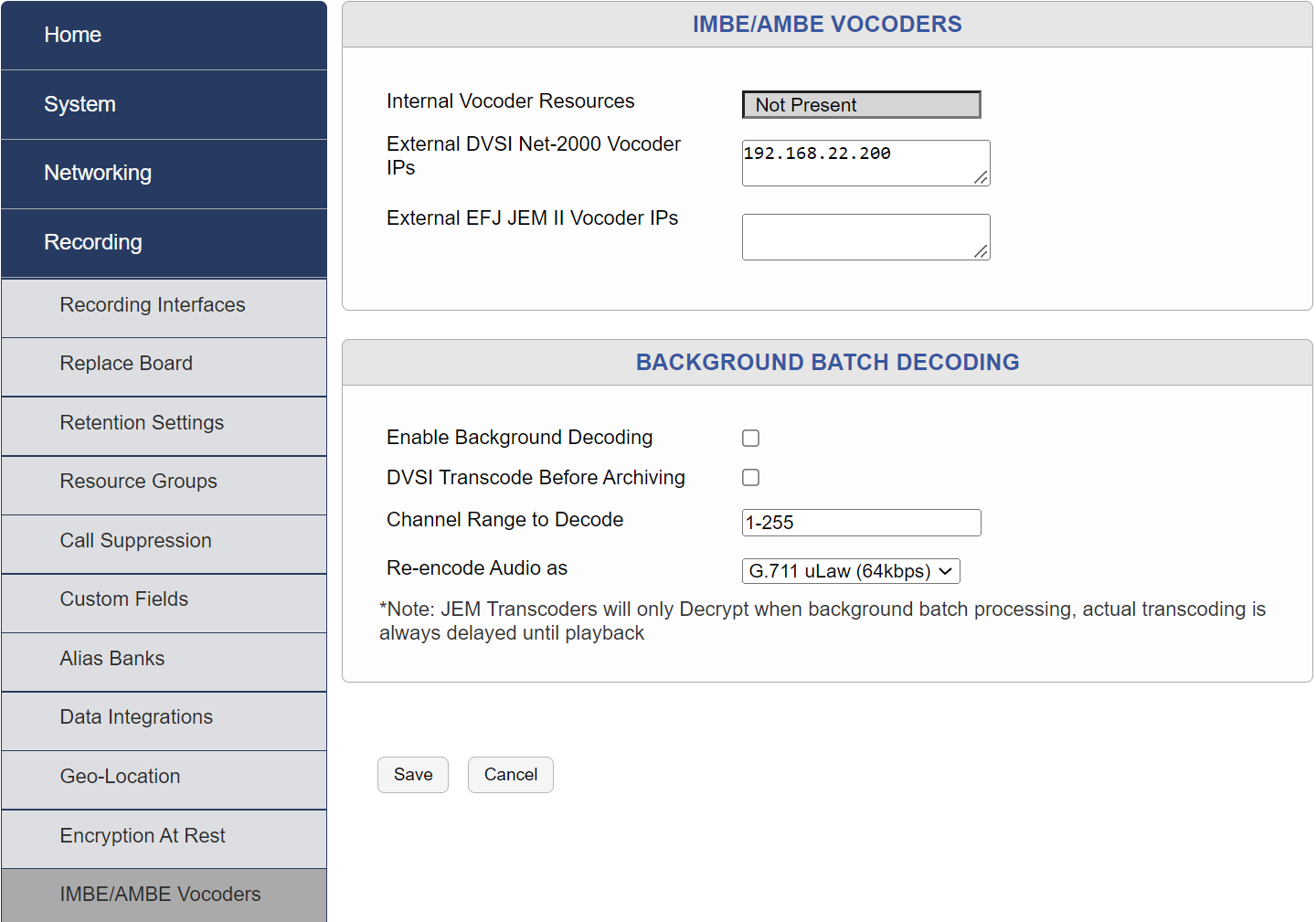
Fig. 6.94 IMBE/AMBE Vocoder Settings
Internal Vocoder Resources: If there are internal vocoders, they should be auto-detected. If not, there should be a check box available to detect them. Once completed skip to the “BACKGROUND BATCH DECODING” Section.
External EFJ JEM II Vocoder IPs: Not Applicable for Capacity Max recording (EF Johnson P25 Recoding only) Leave Blank.
6.13.2.4. Background Batch Decoding
Enable Backgroud Decoding: This is an optional setting that allows AMBE+2 encoded calls to be decoded while the DVSI vocoder resources are not being used. If this is unchecked, the vocoding will occur when a call is selected for replay from MediaWorks DX.
Channel Range to Decode: Range of channels in the system to apply the background decoding.
Re-encode Audio as: Select the encoding algorithm that you would like the AMBE+2 recordings to be re-encoded as.
6.13.2.5. Check for Alerts
Check the NexLog front panel and/or configuration manager (figure below) for any system alerts or CAPACITY MAX-specific alerts. There will be alerts specific to the CAPACITY MAX integration if there are problems saving the template data.
6.13.2.6. Verify Recording
Place a series of test calls between radios on both encrypted and unencrypted talk groups. Use MediaWorks DX or the front panel display to verify the recording of all test calls.