6.14. Omnitronics Recording
6.14.1. Omnitronics Recording Introduction
This application note discusses how to configure the NexLog DX-Series to record VoIP audio from Omnitronics VoIP products. The NexLog DX-Series is a VoIP recorder that is capable of recording and play-back of audio sent to/from Omnitronics VoIP products such as IPR100, IPR110+, IPR400, DRG100, DRG200i1, omnicore Console, RediTALK-Flex, altusomni IPE (REC mode), DX-Altus IPE (REC mode), and TetraGateway-DM.
Note
DRG200i is only available on special request; please contact your Omnitronics representative for information.
6.14.1.1. Methods of Recording Audio
There are a couple of ways in which audio from Omnitronics VoIP devices can be sent to the recorder as follows:
Port mirroring - The local network duplicates network traffic going to/from one Ethernet port (Omnitronics device) to another port (Eventide Nexlog recorder). The advantage of this method is that no configuration changes are needed in the Omnitronics device(s), as audio is duplicated as-is to the recorder. However, since this method requires special configuration of the Ethernet switch, and since there are numerous Ethernet switch manufacturers and methods to achieve this with some requiring a high level of expertise, this application note will not cover port mirroring. You are welcome to configure your network and recorder this way when conferencing is not an option.
VoIP conferencing/forwarding - The Omnitronics device is configured to conference/forward all audio to the Eventide Nexlog recorder IP address and port number. This is the method that is described in this application note.
6.14.2. Recorder Configuration
To configure the NexLog DX-Series, you use its web-based configuration interface. You can access the interface by browsing the recorder’s IP address using a web browser.
If you intend to configure an NexLog DX-Series that is brand new from the factory, its typical default IP address is 192.168.1.101, however, it may be different from this—consult your Eventide documentation for further information if you are unsure. Usually, only one of the Ethernet ports is enabled (the others are usually disabled) by default, so you will need to connect at least one Ethernet cable to the first port to begin. Virtualized NexLog DX-Series recorders have their IP address specified during installation.
6.14.2.1. Logging in to the Recorder
You must ensure that the computer is on the same network subnet as the NexLog DX Recorder otherwise, you cannot connect to the configuration manager.
To login to the NexLog DX Recorder configuration manager:
Type the IP address of the Eventide NexLog DX Recorder into your web browser.
Once you have connected to the recorder, you should see the NexLog DX Series opening page for MediaWorks.
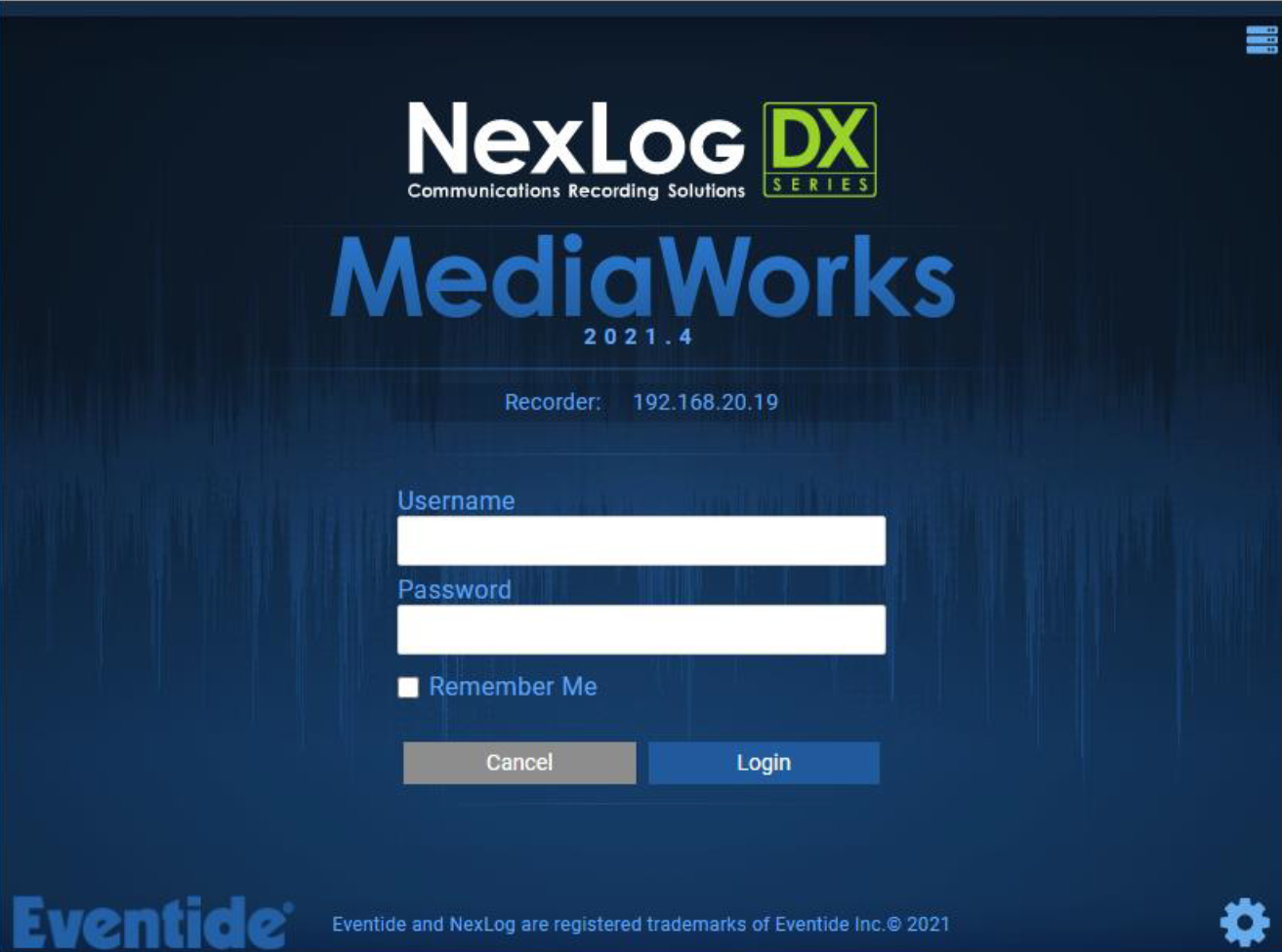
Fig. 6.95 Template Field Details
Use MediaWorks to play back or export recorded audio—please refer to the NexLog DX-Series for detailed configuration and playback instructions not covered by this application note.
On the opening page, select the settings icon (in the lower right) to show the LOGIN page for the configuration interface.
At the LOGIN page, type your username and password and then select Login
the default username is “Eventide” and the password is the serial number of your recorder
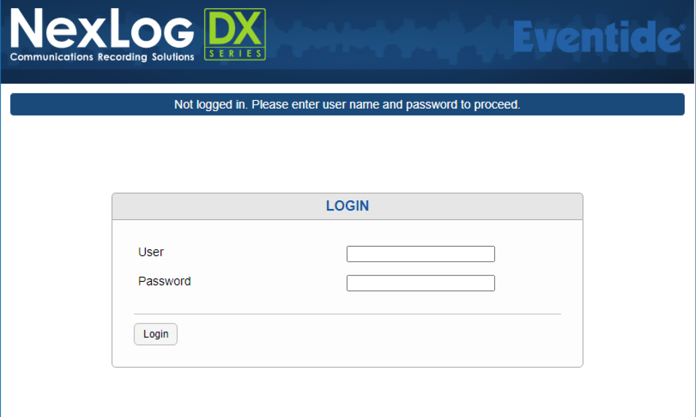
Fig. 6.96 Template Field Details
Once you have logged in, the Home page appears showing details about your recorder.
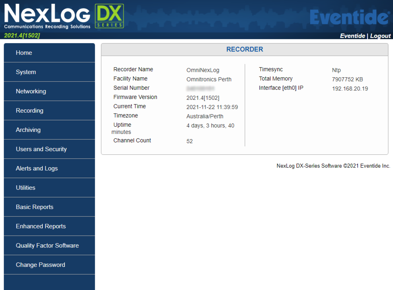
Fig. 6.97 Template Field Details
6.14.2.2. Recorder Configuration Methods
This section applies to setting up the NexLog DX-Series Recorders to record audio to and from the following Omnitronics products: IPR100, IPR110+, IPR400, DRG100 (all variants), DRG200i (all variants), altusomni IPE (REC mode), DX-Altus IPE (REC mode), and TetraGateway-DM.
6.14.2.3. Configuring the NexLog DX Recorder
Use this method to configure the Eventide NexLog DX Recorder. Once you have enabled metadata recording in the DRG, you can commence configuration of the NexLog DX-Series recorder using the procedure below
To configure the Eventide NexLog DX Recorder
Login to the Configuration Manager
On the menu, select Recording, and then select Recording Interfaces
This displays the analog recording interfaces installed (if any) as well as virtual recording interfaces, which must be created and configured to record audio from Omnitronics devices.
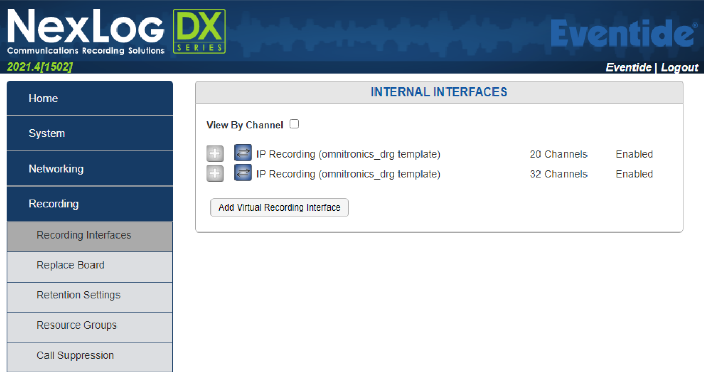
Fig. 6.98 Template Field Details
Select Add Virtual Recording Interface to show the ADD INTERFACE page
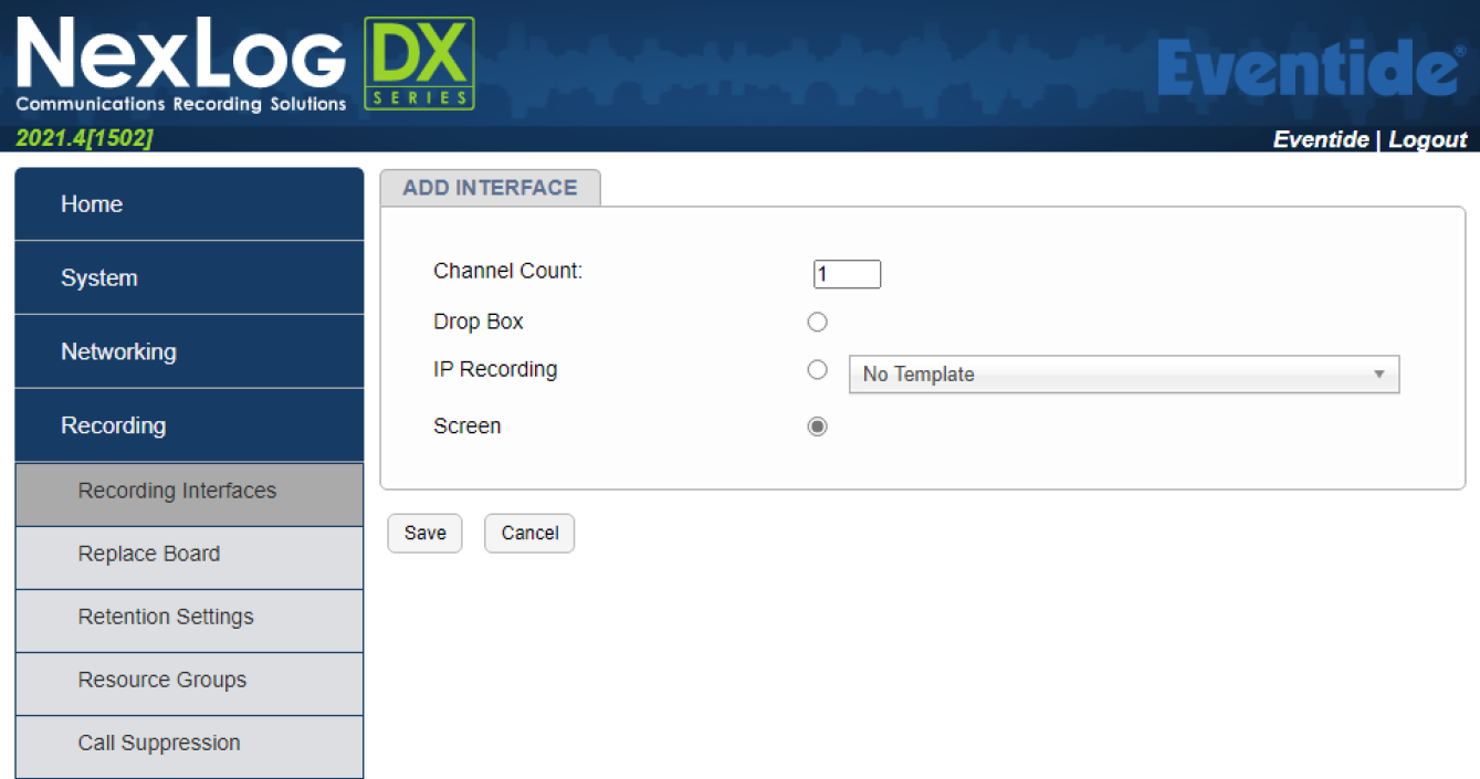
Fig. 6.99 Template Field Details
On the ADD INTERFACE tab, configure the following settings:
Set Channel Count to the total number of VoIP channels you want to record from Omnitronics devices.
For example, a system comprising 2 x IPR100 (2), 3 x IPR110+ (3), 2 x DRG100 (2), 2 x DRG200i (4), 2 x IPR400 (8), and 1 x IPE (8) (altusomni or DX-Altus), the total number of VoIP channels is 27 (2+3+2+4+8+8 = 27).
Omnitronics Device | Channel Count |
|---|---|
IPR100, IPR110+, DRG100 | 1 |
DRG200i | 2 |
IPR400 | 4 |
altusomni or DX-Altus IPE (in REC mode) | 8 |
TetraGateway-DM | 32 |
Select IP Recording for the interface mode, and then select Omnitronics Recording from the dropdown list.
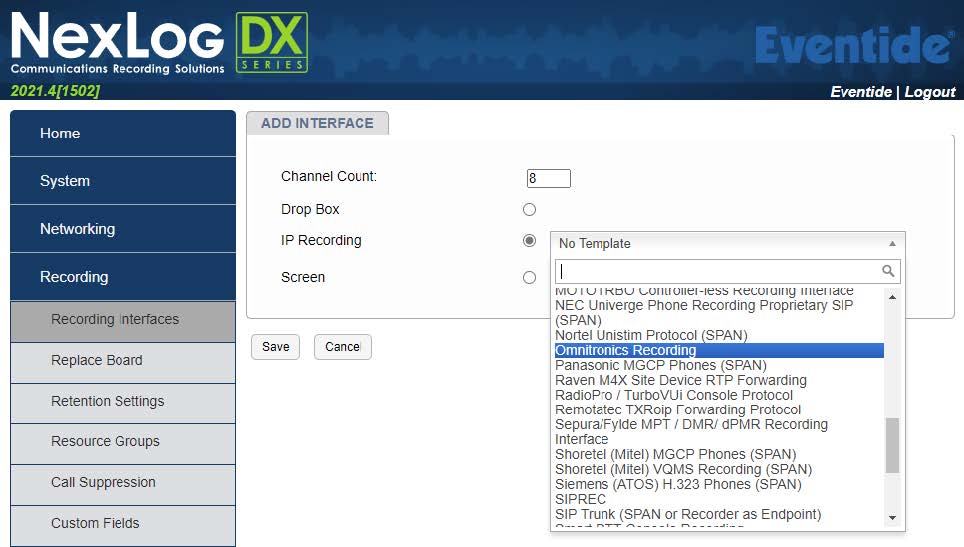
Fig. 6.100 Template Field Details
On the OMNITRONICS RECORDING tab, for the Ethernet Device, select the Eventide Nexlog DX Recorder associated with the same network as the Omnitronics gateway device.
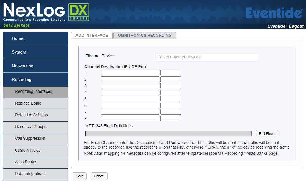
Fig. 6.101 Template Field Details
Under Channel Destination IP UDP Port for each channel, type the IP address of the Eventide Nexlog DX Recorder in the first textbox, and then type the port number on which the recorder will listen to the Omnitronics gateway device in the second textbox. If you are recording a device sending audio to a multicast IP address, enter the multicast IP address and port instead.
Note
Since the Omnitronics IPR/DRG gateway recording interface is tied to a network interface that has a particular IP address (e.g., eth0), the same IP address should be entered for all the channels here (except for multicast recording). If you need to record Omnitronics devices located across multiple ethernet interfaces/subnets of the Eventide system, you will need to create separate Omnitronics Recording interfaces that will be tied to those interfaces and IP addresses.
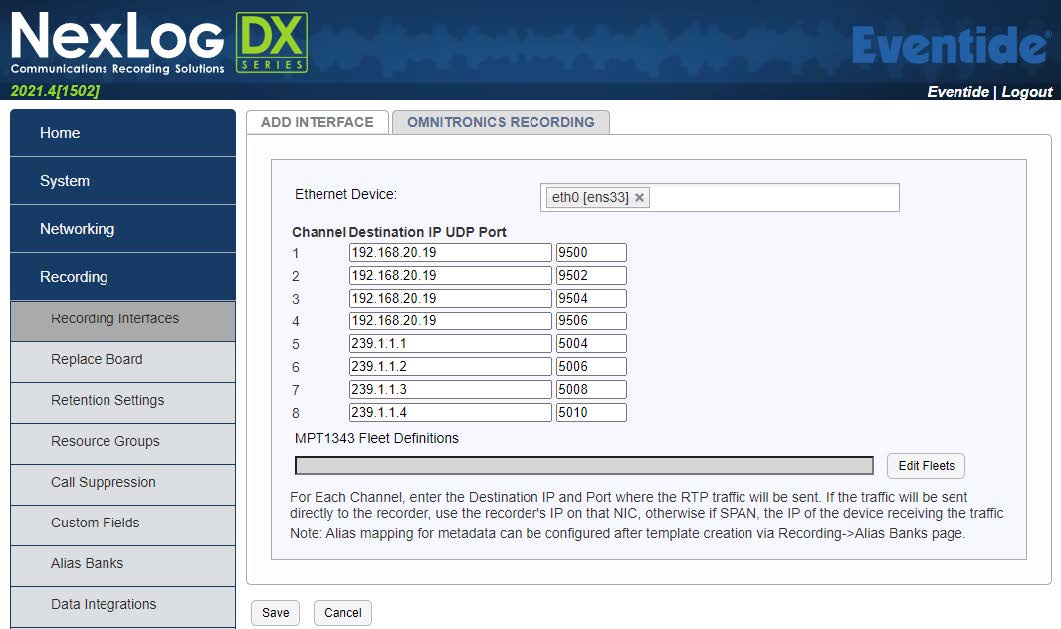
Fig. 6.102 Template Field Details
Note
You must specify the port on which the Omnitronics gateway device will send audio. The port number must satisfy the following: - Must not be a well-known port number (0 to 1024). - Must be an even number - Must be a unique port number for each device configuration and for the Eventide Nexlog recorder (do not use the same port number for recording different devices or ports and do not set it to the same port number used elsewhere in the VoIP/RTP or SIP or digital radio configuration for the device)
(Optional) If you need to record a Tait DMR-AIS system that uses MPT1343 Fleet definitions, select Edit Fleets to define fleet definitions for this recording interface, and configure your fleet definitions as follows:
Enter the fleet prefix in the Prefix textbox, the Fleet Individual Number (FIN) in the FIN textbox, the Fleet Group Number (FGN) in the FGN textbox, the Number of Units in the Num Units textbox, the Number of Groups in the Num Groups text box, and the Digits in the Digits textbox (all fields are mandatory)
If you have more than one fleet definition, select Add to add additional fleets to the list
Select Populate to add your MPT1343 fleet(s) to the recording board interface (the fleets will be populated in the MPT1343 Fleet Definitions text box)
If you need to remove any fleets from the populated list, select Delete next to the fleet definition, and then select Populate once more
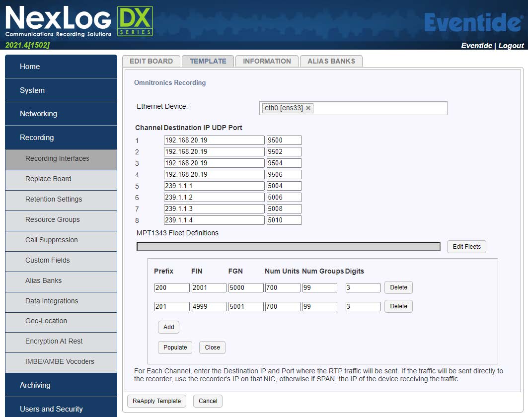
Fig. 6.103 Template Field Details
Note
The fleet definition will apply to all recording IP addresses listed in the recording board. Ensure only DRGs interfaced to Tait DMR-AIS systems with MPT1343 fleets applied are included in the recording board.
Select Save to add the virtual interface to the recorder
This will take you back to the Boards page and the new interface will be available in the list.
Select the “+” next to the new interface to view the interface information.
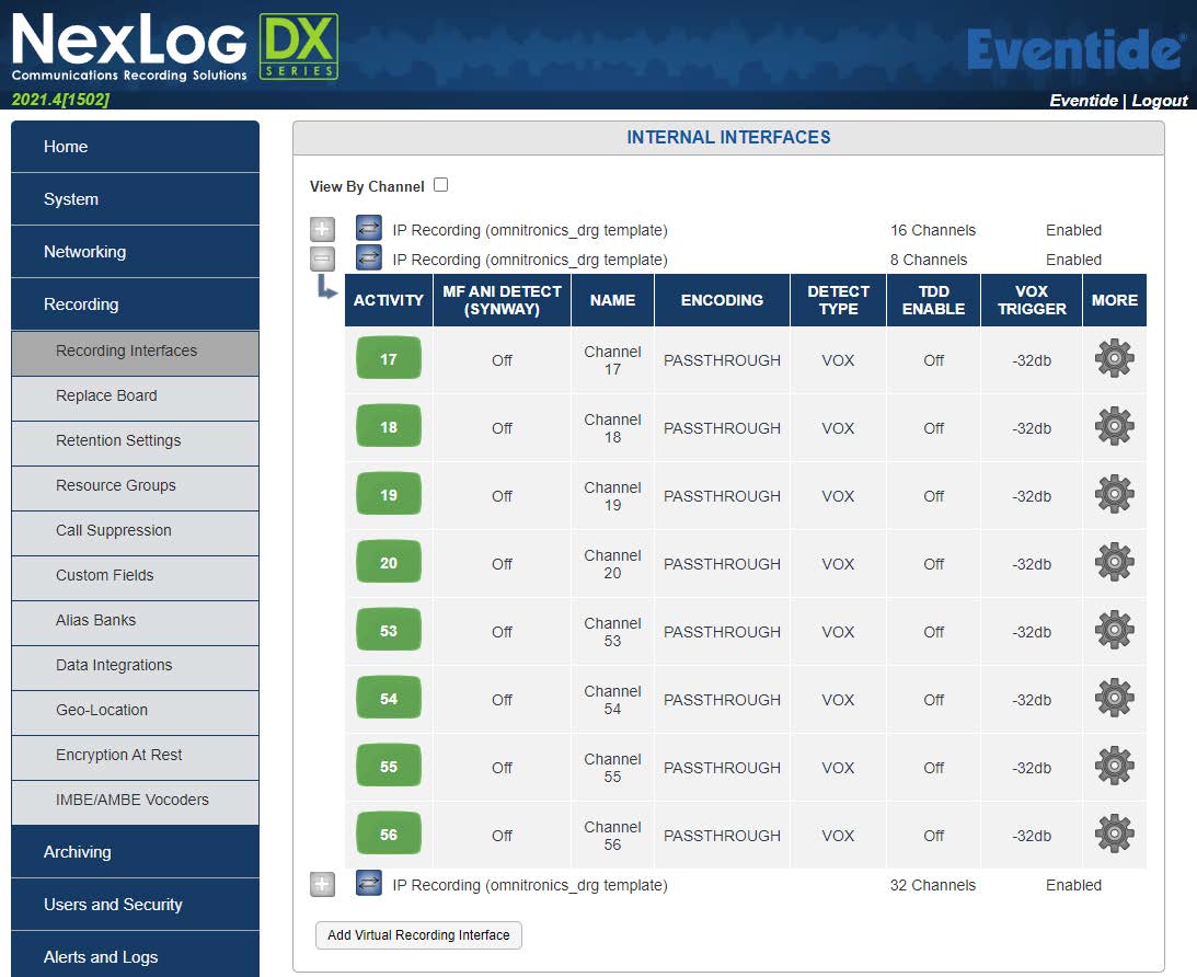
Fig. 6.104 Template Field Details
Optional: To change the name for a channel, select the current name of the channel, and then type a new name in the textbox (e.g., “Example Site”).
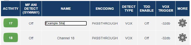
Fig. 6.105 Template Field Details
Press Enter (or select on a blank space away from the name textbox) to save the configuration.
Configuration is now complete for the Eventide Nexlog recorder. The ACTIVITY column shows the recording status for a particular channel (green: idle; red: recording).
Optional: Configure Digital Radio Alias Banks
This optional step can only be performed on Nexlog DX-Series recorders. If you are recording digital radio metadata from a supported Omnitronics DRG, the Nexlog DX will record source and destination caller (radio) IDs as raw numbers, t]alk-group numbers as “GROUP_nnn” (e.g., GROUP_101), and all calls as “ALL_CALL”.
The following example screenshot from MediaWorks shows these default naming schemes for individual, group, and all calls. Note that the “Caller Id” column is the source radio ID, and the “Dtmf” column is the destination radio ID or group.
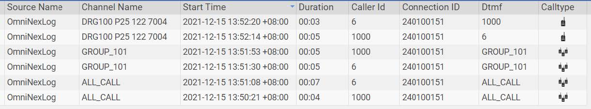
Fig. 6.106 Template Field Details
If you wish to customize the default naming scheme so that the Nexlog recorder displays names instead of numbers, the Alias Banks feature may be used. Separate Alias Banks for Radio IDs and Talk Group/All Call numbers must be made.
6.14.2.3.1. Configure an Alias Bank for Radio IDs
To show names for your radio IDs instead of numbers, you can configure an alias bank for radio IDs. To configure an alias bank
Login to the Configuration Manager (see “Log in to NexLog DX Recorder” on page 3)
On the menu, select Recording, select Alias Banks, then Add Alias Bank
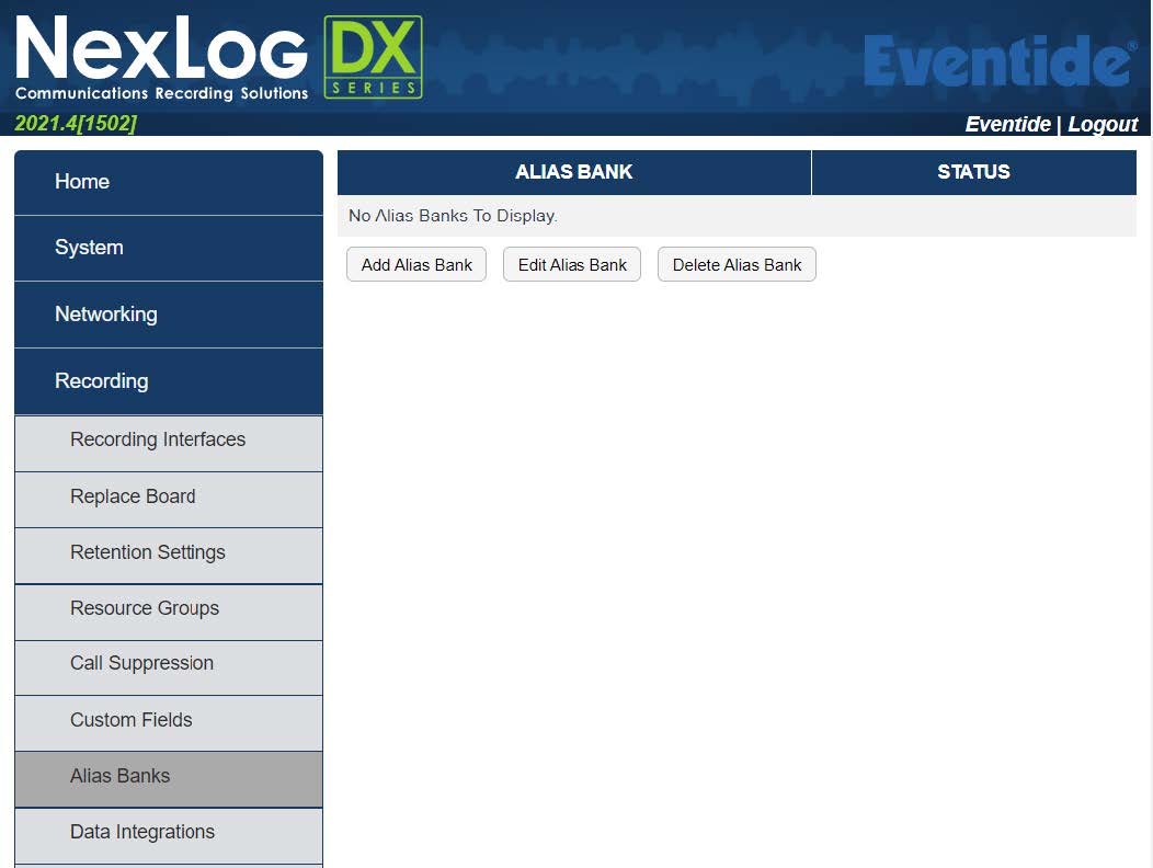
Fig. 6.107 Template Field Details
On the Alias Bank screen: 3.1 Set the Alias Bank Name e.g., “Radio IDs to names”.
Leave the Output Formatter as {{ALIAS}}.
Set both Alias From and Alias To as “CALLER_ID”.
Leave Only Apply Aliases If unchecked.
In Applied Channels, check the box next to each IP Recording (Omnitronics template) board that is receiving the digital radio IDs. If you are unsure, select all of them.
In the Alias Rules section, set the raw radio ID numbers in the Source column, and their desired name in the Alias column.
Alternatively, you may import a .csv list of radio IDs and names using the Import Rules Button. Ensure the first column contains only radio IDs, and the second column contains only the names (do not include table headers). The following example is a .csv file edited with Microsoft Excel in this format: Graphical user interface, text, application, chat, or text message
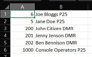
Fig. 6.108 Template Field Details
Description automatically generated
Once you have entered (or imported) all the IDs and their desired names, select Submit to save the changes.
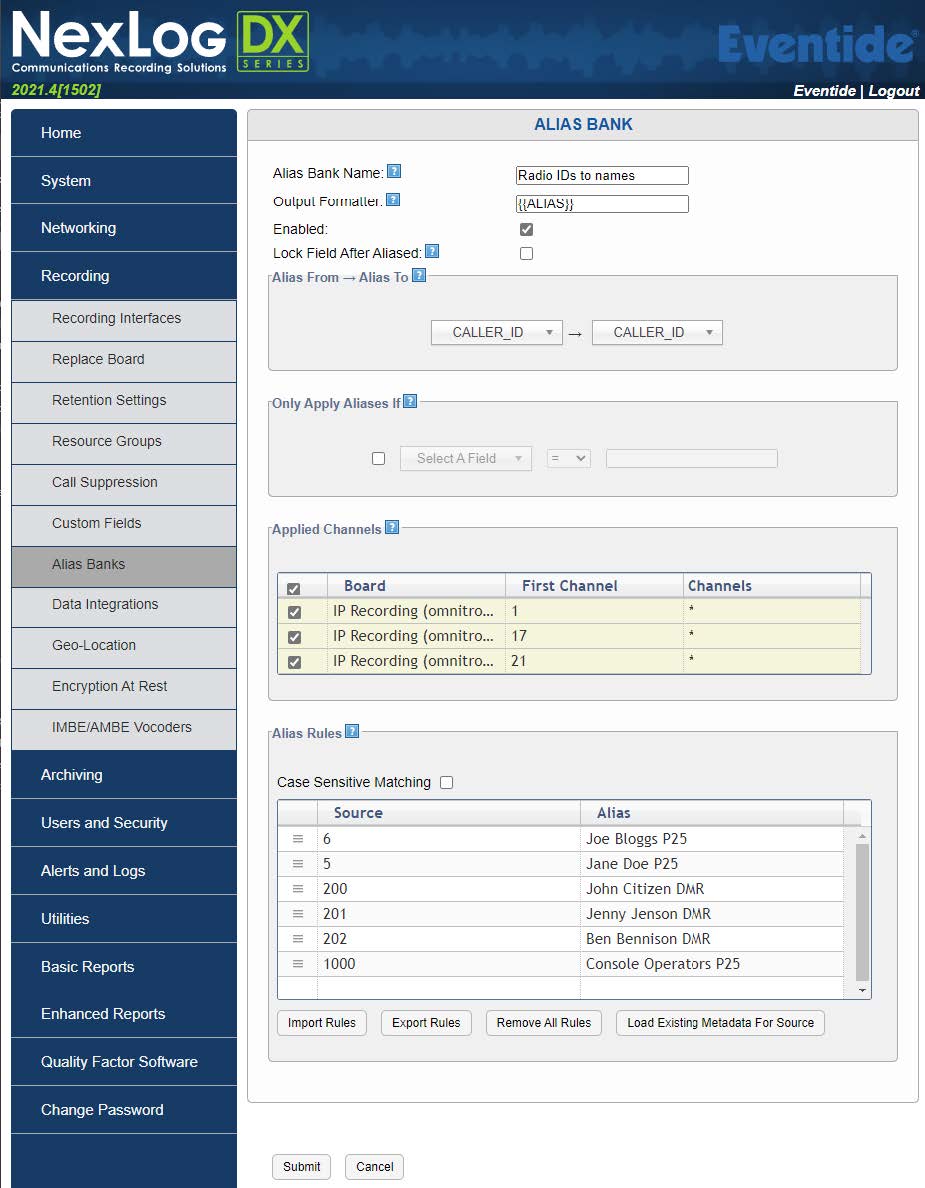
Fig. 6.109 Template Field Details
Note
Only new radio calls made after the configuration has been saved will have their IDs converted to the names defined in the Alias Bank.
6.14.2.3.2. Configure an Alias Bank for Talk Group/All Call IDs
To show names for your Talk Group/All Call IDs instead of numbers, you can configure an alias bank for Talk Group/All Call IDs. To configure alias bank for Talk Group/All Call IDs
Login to the Configuration Manager (see “Log in to NexLog DX Recorder” on page 3)
On the menu, select Recording, select Alias Banks, then Add Alias Bank
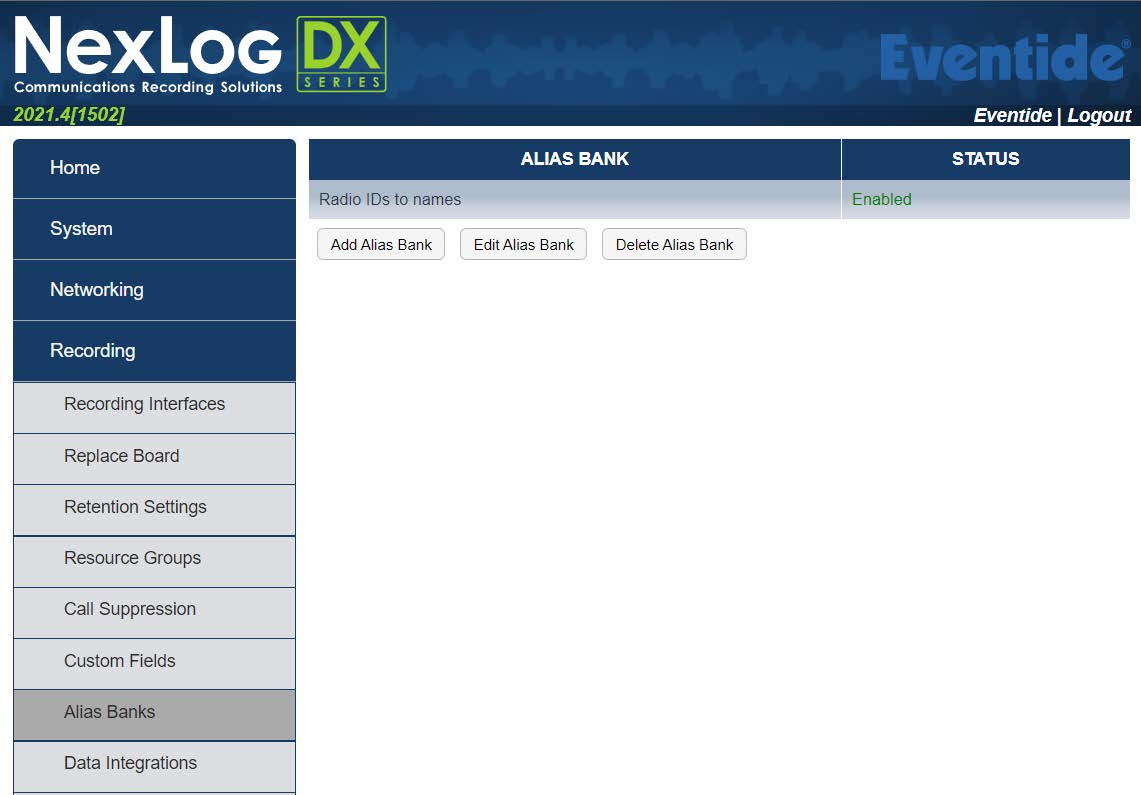
Fig. 6.110 Template Field Details
On the Alias Bank screen:
Set the Alias Bank Name e.g. “Talkgroup IDs to names”
Leave the Output Formatter as {{ALIAS}}
Set both Alias From and Alias To as “DTMF”
Leave Only Apply Aliases If unchecked
In Applied Channels, check the box next to each IP Recording (Omnitronics template) board that is receiving the digital radio IDs. If you are unsure, select all of them.
In the Alias Rules section, set the Source column to your group numbers in the format “GROUP_nnn” (e.g., GROUP_101) to match the raw talk group number. To change All Call naming, set this to “ALL_CALL”. Set the Alias column to the new desired group- or all-call name.
Alternatively, you may import a .csv list of talk group IDs and names using the Import Rules Button. Ensure the first column contains the group numbers in the format “GROUP_nnn” (use “ALL_CALL” for All Call naming), and the second column contains only the desired names (do not include table headers). The following example is a .csv file edited with Microsoft Excel in this format: Graphical user interface, text, application, table, Excel
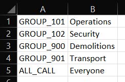
Fig. 6.111 Template Field Details
Once you have entered (or imported) all the groups and their desired names, select Submit to save the changes.
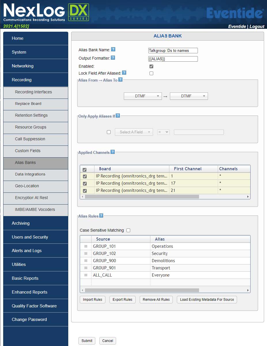
Fig. 6.112 Template Field Details
Note
Only new radio calls made after the configuration has been saved will have their IDs converted to the names defined in the Alias Bank.
If your system is configured to make individual calls, Nexlog DX will place the individual call recipient in the “Dtmf” column, which will be a radio ID. Additional “DTMF” Alias Bank entries will need to be made should you wish to convert the individual call recipient to a name, where the Source is set to the raw radio ID, and Alias is set to the name of the radio.
6.14.2.3.3. Verify Alias Bank Names
Before verifying the applied alias bank rules, you must make at least one digital radio call on a configured ID/talk group before continuing.
Login to the MediaWorks DX web page for your recorder, then observe the “Caller Id” and “Dtmf” columns. Verify new radio calls made contain your configured names:
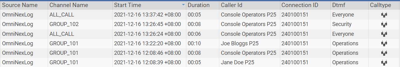
Fig. 6.113 Template Field Details
6.14.3. Omnitronics Device Configuration
This section deals with configuring Omnitronics devices to send audio to the Eventide Nexlog recorder.
6.14.3.1. IPR100, IPR110+, DRG100, DRG200i
Use the following procedure to configure IPR100, IPR110+, DRG100, and DRG200i devices.
To configure IPR100/IPR110+/DRG100/DRG200i devices
Using your web browser, log in to the Omnitronics IPR or DRG device you want to add to the recorder interface
Select Go to ADVANCED mode
On the menu, select VoIP/RTP to display the VoIP/RTP Configuration page
(DRG100 and DRG200i only) Select the option Enable digital radio RTP extension
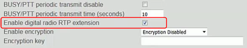
Fig. 6.114 Template Field Details
Note
Not all DRG100 and DRG200i firmware versions/variants support this option. Non-support for this option will not affect the operation of conference mode or audio forwarding to the recorder.
Under Conference Mode, do the following:
Select the Enable conferencing option to enable Conference Mode
For the Conference Mode, select Bridge server: audio linked
For the next available IP address, select the Enable option
In the IP Address text box, type the IP address of the Eventide Nexlog Recorder.
In the Transmit Port text box, type the port on which the gateway will transmit (this is the port that was configured for this device in the recorder configuration)
In this example, the recorder’s IP address is 192.168.20.18 and the port number for recorder is 7050.
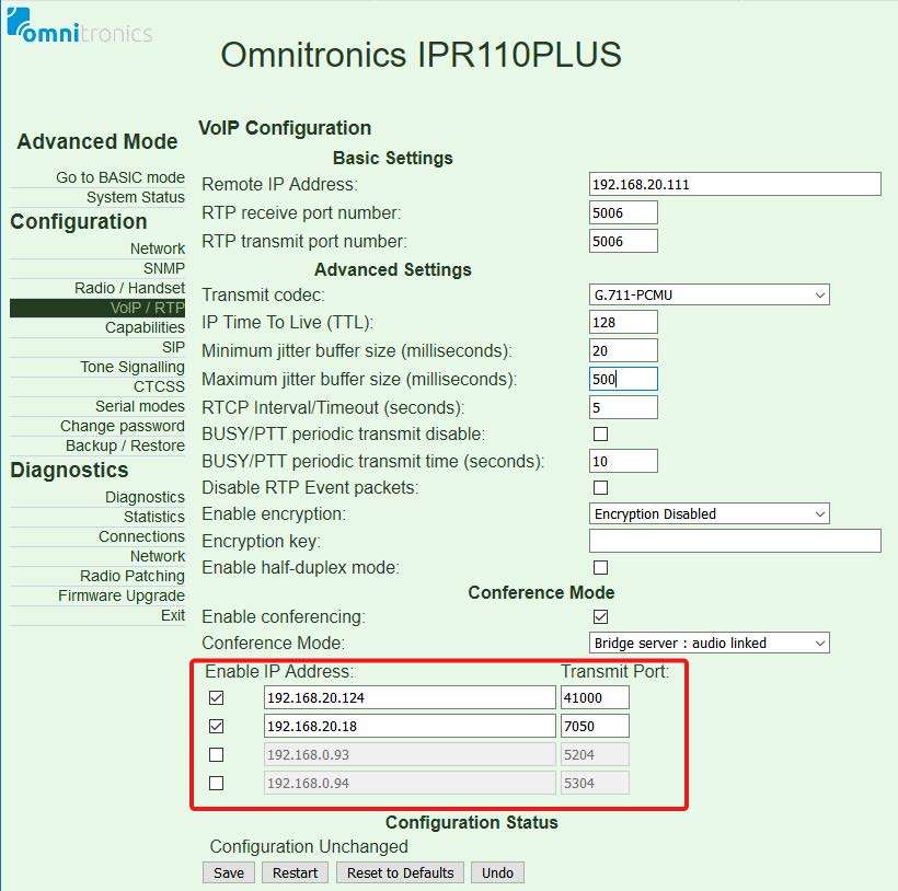
Fig. 6.115 Template Field Details
Select Save to save the configuration, and then select Restart for the changes to take effect.
Configuration of the IPR100/IPR110+/DRG100/DRG200i is now complete.
6.14.3.2. IPR400
Use the following procedure to configure IPR400/IPR400S2 device.
To configure IPR400 device
Using your web browser, log in to the Omnitronics IPR400 device you want to add to the recorder interface.
Under the Audio/Channel menu, select VoIP/RTP to display the VoIP/RTP Configuration for Channel 1.
Under Conference Mode, do the following:
Select the Enable conferencing option to enable Conference Mode
For the Conference Mode, select Bridge server: audio linked
For the next available IP address, select the Enable option
In the IP Address text box, type the IP address of the Eventide Nexlog Recorder
In the Transmit Port text box, type port on which the IPR400 will transmit (this is the port that was configured for this device in the recorder configuration)
In this example, the recorder’s IP address is 192.168.20.18 and the configured port number for recording is 7060:
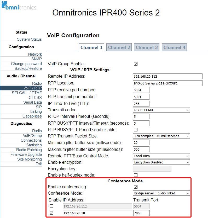
Fig. 6.116 Template Field Details
Select Save to save the configuration for this channel.
Select the tab for the next channel, and then repeat steps 3 and 4 to configure that channel.
Note
Ensure that the Transmit Port number is different from any other IPR400 channel, and the port numbers match those configured in the Eventide Nexlog configuration.
Select Restart for the changes to take effect.
Configuration of the IPR400 is now complete.
6.14.3.3. DX-Altus IPE
Note
The following procedure assumes that the DX-Altus system already has an IPE (in Recorder mode) installed and added to the Local Device configuration tab of the SCU. Refer to the DX-Altus Installation Guide for further configuration information.
To configure the DX-Altus IPE
Using a web browser, browse to the Main SCU IP address and log in.
Select Settings to expand the menu, and then select Devices to display the Devices page (the Local Devices page is selected by default).
On the Local Devices page, select the IPE in Recorder mode, and then select Edit.
Select the Recorder1 tab to display the page for Recorder1.
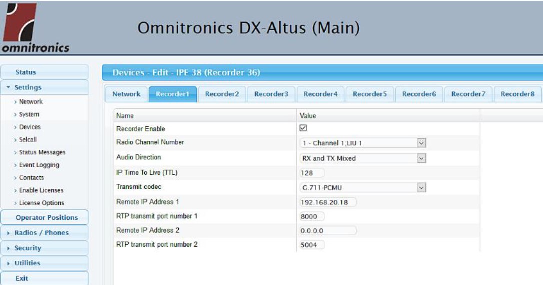
Fig. 6.117 Template Field Details
Configure the recorder settings as follows:
Recorder Enable: Selected
Radio Channel Number: The DX-Altus system channel you want to record
Audio Direction: TX, or RX, or TX and RX mixed
IP Time To Live and Transmit Codec: 128 (default)
Remote IP Address 1: IP address of the Eventide NexLog recorder
RTP transmit port number 1: TX port number configured in the Eventide NexLog recorder configuration
Remote IP Address 2 and RTP transmit port number 2: (Optional) The IP address and port number of a secondary VoIP recorder
Repeat steps 4 and 5 to configure the other channels (up to the 8 channels) of the IPE recorder.
Select Save to save the configuration.
Under the Settings menu, select Devices to display the Devices page (the Local Devices page is selected by default).
On the Local Devices page, select the checkbox in the Restart column for the IPE in Recorder mode.
Select Save to complete configuration.
6.14.3.4. altusomni IPE
Note
The following procedure assumes that the altusomni system already has an IPE (in Recorder mode) installed and added to the Local Device configuration tab of the SCU. Refer to the altusomni Technical Manual for further configuration information.
To configure the altusomni IPE
Using a web browser, browse to the Main SCU IP address and log in.
Select Settings to expand the menu, and then select Devices to display the Devices page (the Local Devices page is selected by default).
On the Local Devices page, select the IPE in Recorder mode, and then select Edit.
Select the Recorder1 tab to display the page for Recorder1.
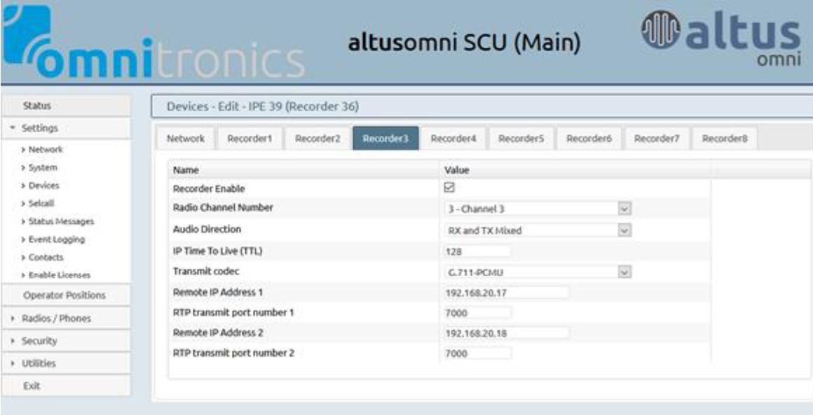
Fig. 6.118 Template Field Details
Configure the recorder settings as follows:
Recorder Enable: Selected
Radio Channel Number: The altusomni system channel you want to record
Audio Direction: TX, or RX, or TX and RX mixed
IP Time To Live and Transmit Codec: 128 (default)
Remote IP Address 1: IP address of the Eventide NexLog recorder
RTP transmit port number 1: TX port number configured in the Eventide NexLog recorder configuration
Remote IP Address 2 and RTP transmit port number 2: (Optional) The IP address and port number of a secondary VoIP recorder
Repeat steps 4 and 5 to configure the other channels (up to the 8 channels) of the IPE recorder.
Select Save to save the configuration.
Under the Settings menu, select Devices to display the Devices page (the Local Devices page is selected by default).
On the Local Devices page, select the checkbox in the Restart column for the IPE in Recorder mode.
Select Save to complete configuration.
6.14.3.5. TetraGateway-DM
Use the following procedure to configure the TetraGateway-DM service.
Note
TetraGateway-DM does not support digital radio RTP extensions at the date of this publication.
To configure Tetra Gateway DM
Using your web browser, log in to the Omnitronics TetraGateway-DM web interface.
Select Settings, then select VoIP Connections.
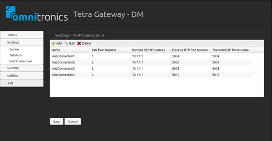
Fig. 6.119 Template Field Details
Select Add to add a new VoIP connection.
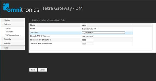
Fig. 6.120 Template Field Details
On the VoIP Connection Edit page, configure the following settings:
Name: Type a name for the Eventide connection
Talk-path: Select the desired TETRA talk-path that you want to record
Remote RTP IP Address: Type the IPv4 address of your Eventide recorder
Receive RTP Port Number and Transmit RTP Port Number: Set these ports to the same recording port number configured in Eventide for this talk-path
Select Save to save the settings.
Repeat steps 2 to 5 to add another TETRA talk-path that you wish to record, ensuring you assign a unique recording RTP port number to each talk-path.
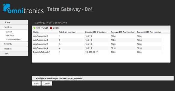
Fig. 6.121 Template Field Details
Note
After adding the Eventide talk-path(s) to the TetraGateway-DM, the service needs to be restarted for the changes to take effect (see procedure below).
To restart the TetraGateway-DM service
On computer running TetraGateway-DM, right-select the taskbar and select Task Manager
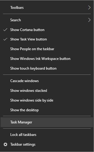
Fig. 6.122 Template Field Details
On the Task Manager window, select the Services tab.
In the list of services, right-click Omnitronics TetraGateway-DM and select Restart.
The service should restart after several seconds.
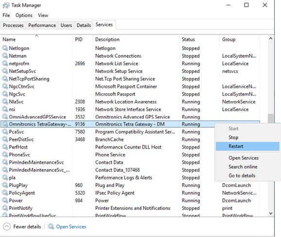
Fig. 6.123 Template Field Details