7.7.6. GPIO
General-Purpose Input/Output (or GPIO) offers the ability to integrate third-party circuitry such as analog inputs, stack lighting, buzzers, and indicators into and out of the NexLog DX-Series system.
The GPIO board can be used for the following functions:
The start and stop of recording on a channel can be triggered by a GPIO board input signal. (For more information, see Section 7.3.1 Recording Interfaces.) The logic of GPIO-triggered recording can be customized using the custom script feature.
A recorder alert can trigger a GPIO output signal. Alerts of severity 3 or 4 (Error or Severe) will by default trigger a signal on the first output pair of the board. Further customization is possible via a custom integration script available from Eventide.
License Required
This feature must be licensed to be used. Contact your Eventide Communications Dealer for assistance.
To configure your GPIO settings, go to the NexLog “Configuration Manager: Alerts and Logs” menu and select GPIO. For each GPIO board in the system there will be an entry on the page with a description of the board, for example “Contec PCI-E (DIO-48D-PE),” the number of the physical slot the board is installed in, and the pin count for each board.
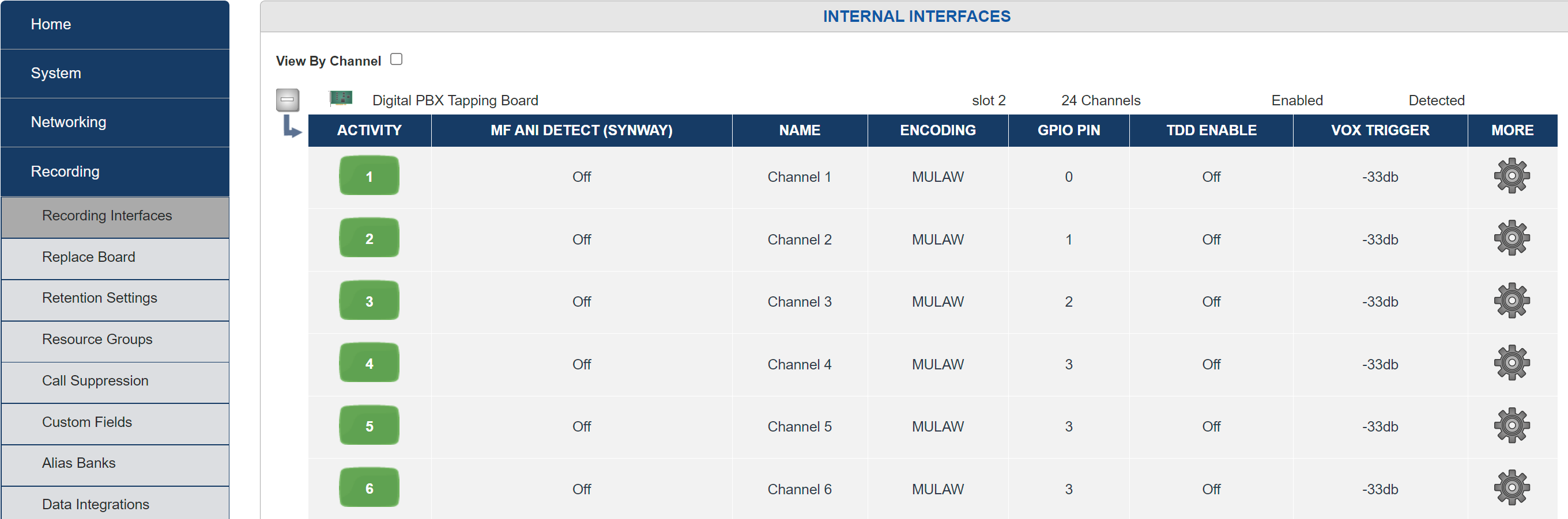
Fig. 7.133 GPIO Board Settings
Click on the Edit Board button for the board you want to configure. For each Pin Block (1-A Port [0-7], 1-B [8-15], 1-C Port (Low)[16-19], etc) you can select the I/O mode to either be Input or Output.
For each input pin, you can configure channels that should record when the pin is active. This can be a single channel, or a comma-delimited list of channels. One limitation: channels can only be controlled by one pin, so you cannot set pin 1 to control 1,2,3 and pin 2 to control 2, because 2 is already configured for pin 1. When configuring a pin for input, the channel’s configured GPIO pin field on the Recording Interfaces page is set, but the detect type still needs to be manually changed to GPIO.
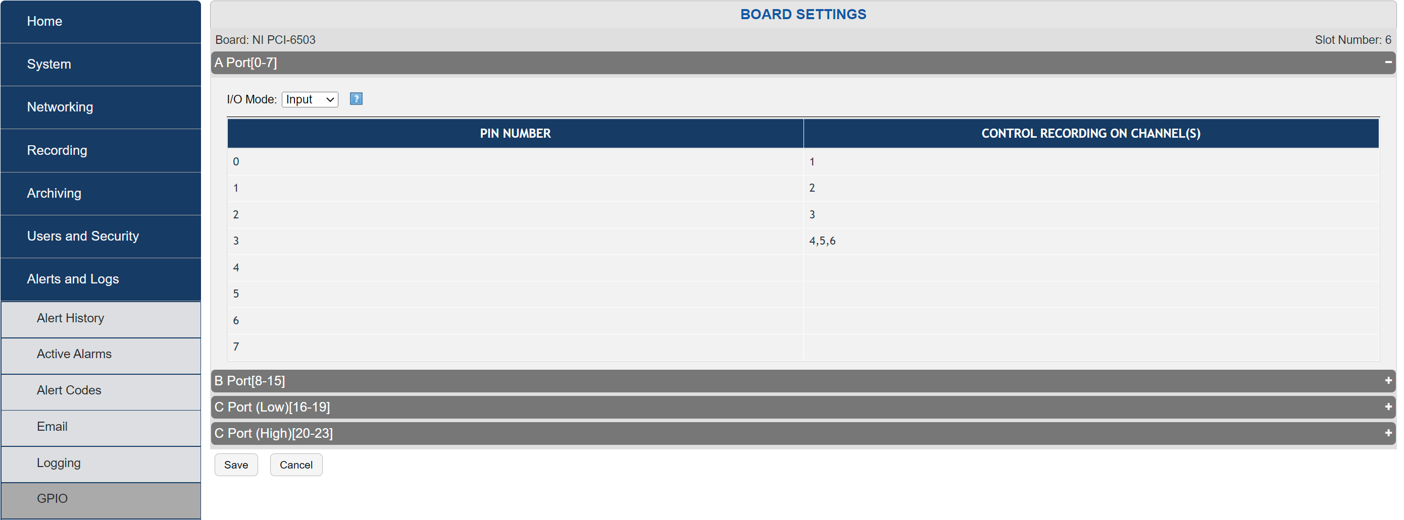
Fig. 7.134 GPIO Input Settings
You can configure pins to trigger an output when an alert of a certain severity is triggered. The alert levels in order of severity are:
Info
Warning
Error
Severe
If configured to alert on “Warning” or above, the pin will remain off for an “Info” alert, but will then turn on for any escalated alert. You can also configure a relay closure only for unacknowledged alarms of those types.
The relay can also be activated by the recorder just being powered on, it will remain active while the recorder is on and turn off when shutdown. If you want a specific alert code to trigger the output, navigate to the Alert Codes page to find the relevant Alert Code, and enter it into the Alert Code(s) entry field.
For example: Alert code 6001 is for a degraded RAID. Enter 6001 in the Alarm Code entry field along with any other necessary Alert Codes, then select “Save” once completed.
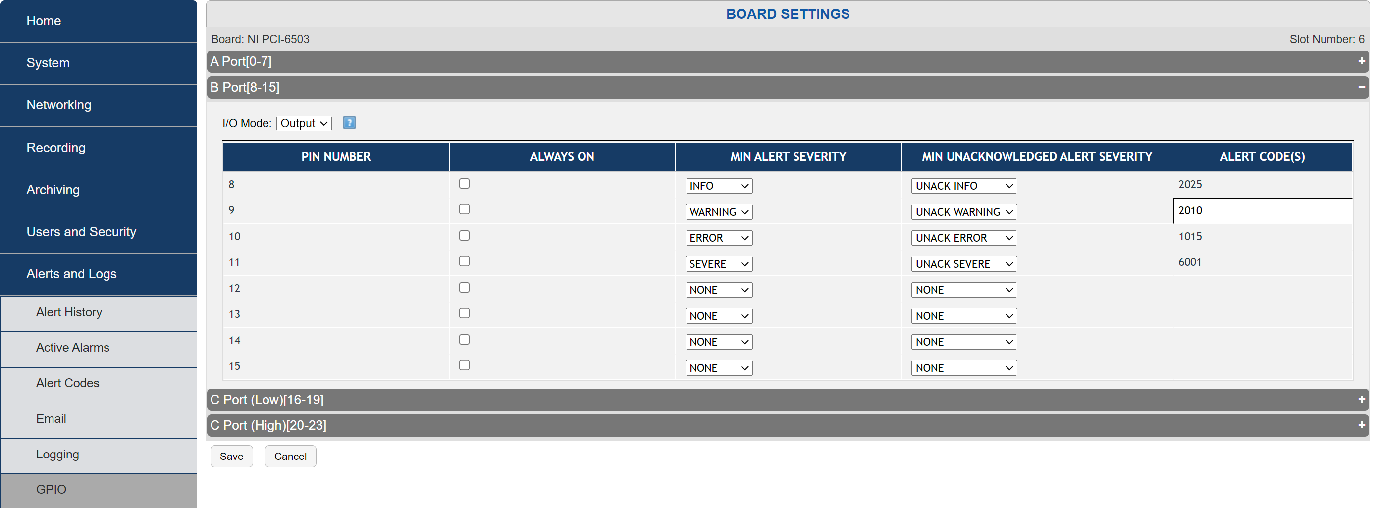
Fig. 7.135 GPIO Output Settings
Multiple rules can be configured for each output, and using boolean logic, these rules are OR’ed together. For example, you may configure Minimum Alert Severity to be SEVERE, and Minimum Unacknoledged Alert Severity to WARNING. In this case, an alert of type ERROR will trigger the pin, but acknowledging it will turn off the pin, but an alert of SEVERITY will cause the pin to trigger until the alert is resolved. The only rule that cannot be combined with other rules is Always On. The pin is always active while the recorder is on if Always On is set, so it does not make sense to use with other rules, as it will never turn off.
Eventide supports the following optional GPIO boards for use with recorders:
National Instruments PCI-6503 Board (24-Channel) (For NexLog 740 DX-Series Recorder only)
Contec DIO-48D-PE Digital I/O PCI Express card (48-Channel)
Important! The specifications for these GPIO boards describe the maximum ratings for their input or output signals. Connections that exceed these maximum ratings can damage the board and the recorder. Neither Eventide, National Instruments, nor Contec are liable for any damages resulting from signal connections that exceed these maximum ratings.
7.7.6.1. National Instruments PCI-6503 Board (24-Channel)
This board provides a 24-bit parallel, digital I/O interface with:
24 static digital I/O lines (non-isolated 5 V TTL/CMOS) in 4-bit and 8-bit ports, 2.4 mA
50-pin male I/O connector (for ribbon cable with IDC-type connector)
No switches or jumpers
CHANGE THIS Licenses are available for 12 input/12 outputs or 24 inputs
Note: The I/O ports are not optically isolated.
Eventide has adopted static port assignments on the PCI-6503. See *Figure 90—GPIO Board Pin Assignments (NI PCI-6503)* on page 164, which shows the connector pin assignments. For detailed specifications, refer to PCI-6503 on the National Instruments website (www.ni.com).
Figure —GPIO Board Pin Assignments (NI PCI-6503)
C-U | PC7 | 1 | 2 | GND |
|---|---|---|---|---|
PC6 | 3 | 4 | GND | |
PC5 | 5 | 6 | GND | |
PC4 | 7 | 8 | GND | |
C-L | PC3 | 9 | 10 | GND |
PC2 | 11 | 12 | GND | |
PC1 | 13 | 14 | GND | |
PC0 | 15 | 16 | GND | |
B | PB7 | 17 | 18 | GND |
PB6 | 19 | 20 | GND | |
PB5 | 21 | 22 | GND | |
PB4 | 23 | 24 | GND | |
PB3 | 25 | 26 | GND | |
PB2 | 27 | 28 | GND | |
PB1 | 29 | 30 | GND | |
PB0 | 31 | 32 | GND | |
A | PA7 | 33 | 34 | GND |
PA6 | 35 | 36 | GND | |
PA5 | 37 | 38 | GND | |
PA4 | 39 | 40 | GND | |
PA3 | 41 | 42 | GND | |
PA2 | 43 | 44 | GND | |
PA1 | 45 | 46 | GND | |
PA0 | 47 | 48 | GND | |
+5V | 49 | 50 | GND |
Eventide supports two modes in which to use the PCI-6503. Each is enabled with a license key. The first mode divides the 24 IO lines as 12 input and 12 output. The second mode uses all 24 lines as input. The static port assignments on the PCI-6503 for the two supported modes are as follows.
12 input mode:
Input pins 0-7: Port A (PA0-PA7); odd numbered pins 47 to 33
Input pins 8-11: Port C upper nibble (PC4-PC7); odd numbered pins 7 to 1
Output pins 0-7: Port B (PB0-PB7); odd numbered pins 31 to 17
Output pins 8-11: Port C lower nibble (PC0-PC3); odd numbered pins 15 to 9
24 input mode:
Input pins 0-7: Port A (PA0-PA7); odd numbered pins 47 to 33
Input pins 8-15: Port B (PB0-PB7); odd numbered pins 31 to 17
Input pins 16-23: Port C (PC0-PC7); odd numbered pins 15 to 1
7.7.6.2. Contec DIO-48D-PE Digital I/O PCI Express card (48-Channel)
This board provides a 48-bit parallel, digital I/O interface with:
48 digital I/O lines (non-isolated 5 V TTL/CMOS) in 4-bit and 8-bit ports, IOL=24mA (Max.) IOH=-15mA (Max.)
50-pin male I/O connector (for ribbon cable with IDC-type connector)
No switches or jumpers
Unique Device Identifier in upper corner farthest from the pin out.
For recorders using more than one of this type of GPIO board, this must be set to a unique number for each board, ideally in ascending order according to slot number.
Licenses are available for 12 input/12 outputs or 24 inputs
Note
The I/O ports are not optically isolated.